
Punching machine

A punching machine, strip technology, applied in the filtration of dispersed particles, transportation and packaging, separation of dispersed particles, etc., can solve the problems of unstable position, misalignment, health hazards of operators, etc., to ensure the operating environment, The effect of improving processing quality and ensuring physical health

Active Publication Date: 2020-07-24
江苏鑫汇金印刷有限公司
View PDF6 Cites 0 Cited by
  • Summary
  • Abstract
  • Description
  • Claims
  • Application Information

AI Technical Summary

Problems solved by technology

[0002] When the paper is punched, it will produce dust particles, etc., which will make the operating environment of the punching equipment bad and cause harm to the health of the operators.
When the paper is punched, the position is not aligned and the position is not stable, which will interfere with the punching process of the paper

Method used


Image

  • Punching machine
  • Punching machine
  • Punching machine

Examples


Embodiment 1

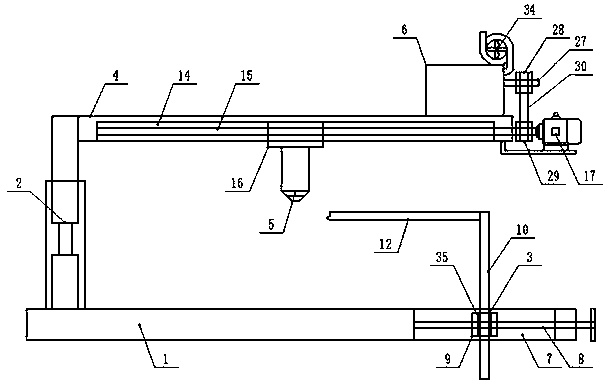
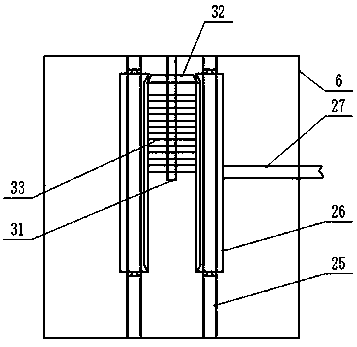
[0016] Embodiment 1: see figure 1 , figure 2 , image 3 , Figure 4 , Figure 5 , a punching machine provided by the present invention is now described, including a base 1, an electric control telescopic support frame 2 is vertically fixed on the upper end of one side of the base 1 in the length direction, and a positioning adjustment mechanism 3 is provided on the other side , the top of the electronically controlled telescopic support frame 2 is fixed with a horizontal support frame 4, the lower end of the horizontal support frame 4 is provided with a punch 5, and the upper end is provided with a dust collection shell 6, and the positioning adjustment mechanism 3 includes a bar-shaped pass The first screw mandrel 8 provided on the middle side of the inner end of the mouth 7 and the strip-shaped opening 7 along the width direction of the inner end, the first screw mandrel 8 moves through the first sliding seat 9 provided, and the first sliding seat 9 outside The baffle p...

Embodiment 2

[0017] Example 2: see figure 1 Now, a punching machine provided by the present invention will be described. The electronically controlled telescopic support frame 2 includes a hollow main frame body vertically fixed on the upper end of the base 1, and a vertically movably inserted top end of the hollow main frame body. The movable secondary frame body and the telescopic cylinder provided between the insertion end of the movable secondary frame body and the bottom end wall of the hollow main frame body, the horizontal support frame 4 is fixed horizontally at the position corresponding to the positioning adjustment mechanism 3, and the horizontal The lower end of the support frame 4 is provided with a strip groove 14 along its length direction, and a fourth screw rod 15 and a strip slide seat 16 are arranged in the strip groove 14, and the fourth screw rod 15 moves through the The bar-shaped sliding seat 16 is designed, and a fourth screw drive assembly is provided between the i...

Embodiment 3

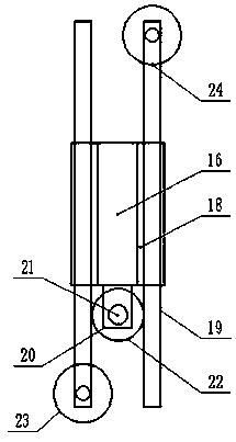
[0018] Embodiment 3: see figure 1 , figure 2, a kind of punching machine provided by the present invention is described now, and the outer end walls of the two sides of the strip-shaped sliding seat 16 along the length direction of the base 1 are respectively provided with strip-shaped slide grooves 18, and the strip-shaped slides Slots 18 are all opened along the width direction of the base 1 and are designed with openings at both ends of the length direction. Bar slide bars 19 are respectively provided in the strip slide grooves 18, and the strip slide seats 16 are arranged along the The outer end wall on one side of the width direction of the base 1 is provided with a rotating shaft installation frame 20, and the upper end of the rotating shaft mounting frame 20 is vertically provided with a rotating shaft 21, and the outer part of the rotating shaft 21 and corresponding to the position of the strip slide bar 19 are covered with a second A gear 22, the first tooth grooves...


PUM


Abstract

The invention discloses a punching machine and relates to the field of paper punching. The punching machine comprises a pedestal, wherein an electric control stretchable supporting frame is verticallyand fixedly arranged at the upper end of one side in the length direction of the pedestal, and a location adjustment mechanism is arrange at the other side in the length direction of the pedestal; ahorizontal supporting frame is fixedly arranged at the top end of the electric control stretchable supporting frame, a punch is arranged at the lower end of the horizontal supporting frame, and a dustcollection shell is arranged at the upper end of the horizontal supporting frame; and the location adjustment mechanism comprises a strip-like through opening, a first lead screw, a first sliding seat, a baffle, a second lead screw, a pressing rod and a third lead screw, wherein the first lead screw is arranged at the middle side of the inner end of the strip-like through opening and in the widthdirection of the inner end of the strip-like through opening, the first lead screw movably penetrates through the first sliding seat, the baffle is vertically arranged on the outer end wall of the first sliding seat, the second lead screw is arranged on the top of the baffle, the pressing rod is horizontally and fixedly arranged at the top side of the baffle, and the third lead screw is vertically arranged at the lower end of the first sliding seat. Through the punching machine, dedusting treatment during paper punching can be realized, an operation environment of equipment is safeguard, thehealth of an operator is safeguarded, alignment and stabilization of to-be-punched paper positions are realized, and processing quality is improved.

Description

technical field [0001] The invention relates to the field of paper punching, in particular to a punching machine. Background technique [0002] When paper is punched, dust particles will be generated, which will make the operating environment of the punching equipment harsh and endanger the health of operators. When the paper is punched, if the position is not aligned and the position is not stable, it will interfere with the punching process of the paper. Therefore, a new solution is now required. Contents of the invention [0003] In order to solve the above problems, the present invention discloses a punching machine, which can realize the dust removal treatment during paper punching processing, ensure the operating environment of the equipment, ensure the health of the operators, and realize the position of the paper to be punched. Alignment, stability, improve processing quality. [0004] In order to achieve the above objectives, the present invention provides the ...

Claims


Application Information

Patent Timeline
Patent Type & Authority Applications(China)
IPC IPC(8): B26F1/02B26D7/02B26D7/18B26D7/26B26D7/28B01D46/42
CPCB26F1/02B26D7/015B26D7/025B26D7/1863B26D7/2628B26D7/28B01D46/681
Inventor 吴克美
Owner 江苏鑫汇金印刷有限公司
Learn More