Efficient heat dissipation injection mold
An injection mold, high-efficiency technology, applied in the field of high-efficiency heat-dissipating injection molds, can solve the problems of long heat dissipation time, poor cooling effect, and affecting the injection molding processing efficiency of products, and achieve the goal of accelerating heat dissipation, improving efficiency, and accelerating molding progress Effect
- Summary
- Abstract
- Description
- Claims
- Application Information
AI Technical Summary
Problems solved by technology
Method used
Image
Examples
Embodiment 1
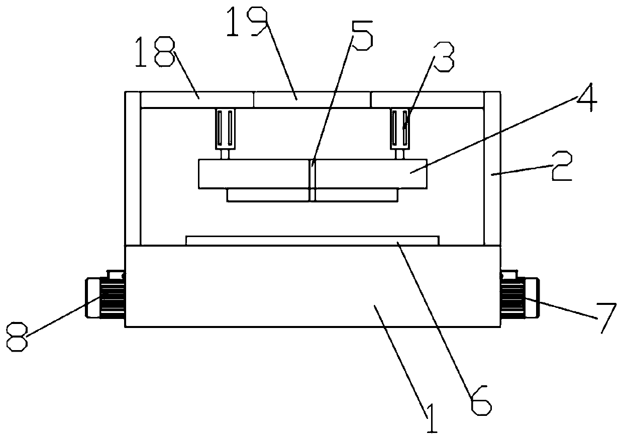
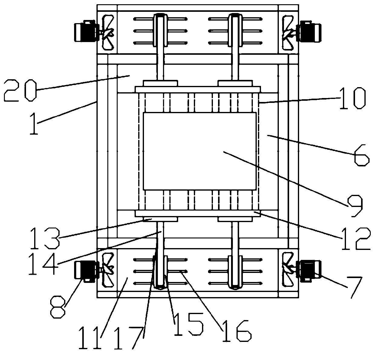
[0028] Such as Figure 1-2 As shown, in the embodiment provided by the present invention, a high-efficiency heat dissipation injection mold includes a base 1, and the base 1 has a mounting groove 20, and a female mold 6 is fixedly installed in the mounting groove 20, and the female mold 6 is fixed in the mounting groove 20. The top surface of the mold 6 has a mold cavity 9; the end top surface of the base 1 is fixedly equipped with a support column 2, and the top of the support column 2 is fixedly provided with a support beam 18, and the bottom surface of the support beam 18 is equipped with a The electric telescopic rod 3 at the height position of the mold 4 in the vertical direction, the male mold 4 is located directly above the female mold 6, and the male mold 4 is also provided with an injection mold that communicates with the mold cavity 9. port 5; the support beam 18 is provided with an operation through hole 19 located directly above the injection port 5;
[0029] Furt...
Embodiment 2
[0032] Such as Figure 1-2 As shown, in the embodiment provided by the present invention, a high-efficiency heat dissipation injection mold includes a base 1, and the base 1 has a mounting groove 20, and a female mold 6 is fixedly installed in the mounting groove 20, and the female mold 6 is fixed in the mounting groove 20. The top surface of the mold 6 has a mold cavity 9; the end top surface of the base 1 is fixedly equipped with a support column 2, and the top of the support column 2 is fixedly provided with a support beam 18, and the bottom surface of the support beam 18 is equipped with a The electric telescopic rod 3 at the height position of the mold 4 in the vertical direction, the male mold 4 is located directly above the female mold 6, and the male mold 4 is also provided with an injection mold that communicates with the mold cavity 9. port 5; the support beam 18 is provided with an operation through hole 19 located directly above the injection port 5;
[0033] Furt...
Embodiment 3
[0039] Such as Figure 1-2 As shown, in the embodiment provided by the present invention, a high-efficiency heat dissipation injection mold includes a base 1, and the base 1 has a mounting groove 20, and a female mold 6 is fixedly installed in the mounting groove 20, and the female mold 6 is fixed in the mounting groove 20. The top surface of the mold 6 has a mold cavity 9; the end top surface of the base 1 is fixedly equipped with a support column 2, and the top of the support column 2 is fixedly provided with a support beam 18, and the bottom surface of the support beam 18 is equipped with a The electric telescopic rod 3 at the height position of the mold 4 in the vertical direction, the male mold 4 is located directly above the female mold 6, and the male mold 4 is also provided with an injection mold that communicates with the mold cavity 9. port 5; the support beam 18 is provided with an operation through hole 19 located directly above the injection port 5;
[0040]Furth...
PUM
 Abstract
Description
Claims
Application Information
 - R&D
- Intellectual Property
- Life Sciences
- Materials
- Tech Scout
- Unparalleled Data Quality
- Higher Quality Content
- 60% Fewer Hallucinations
Browse by: Latest US Patents, China's latest patents, Technical Efficacy Thesaurus, Application Domain, Technology Topic, Popular Technical Reports.
© 2025 PatSnap. All rights reserved.Legal|Privacy policy|Modern Slavery Act Transparency Statement|Sitemap|About US| Contact US: help@patsnap.com


