Spiral buckle type screw-free pressure reducing valve

A pressure reducing valve and screwless technology, which is applied in the field of pressure reducing valves, can solve the problems of low production efficiency and achieve the effect of simple structure, good cost performance and reduced parts

Pending Publication Date: 2020-07-24
樊响
View PDF0 Cites 0 Cited by
  • Summary
  • Abstract
  • Description
  • Claims
  • Application Information

AI Technical Summary

Problems solved by technology

[0003] The technical problem to be solved in the present invention is: to overcome the problem of low production efficiency caused by the use of many screws in the existing U pressure reducing valve dedicated to the integrated waterway plate, and to design a screwless pressure reducing valve with screw buckle to improve production efficiency and meet the market demand. need

Method used


Image

  • Spiral buckle type screw-free pressure reducing valve
  • Spiral buckle type screw-free pressure reducing valve
  • Spiral buckle type screw-free pressure reducing valve

Examples


specific Embodiment approach 1

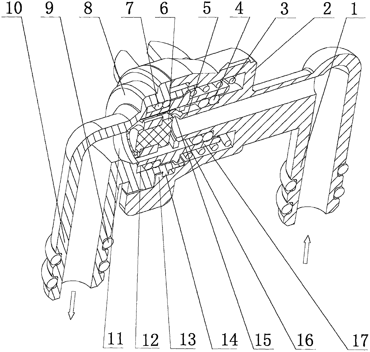
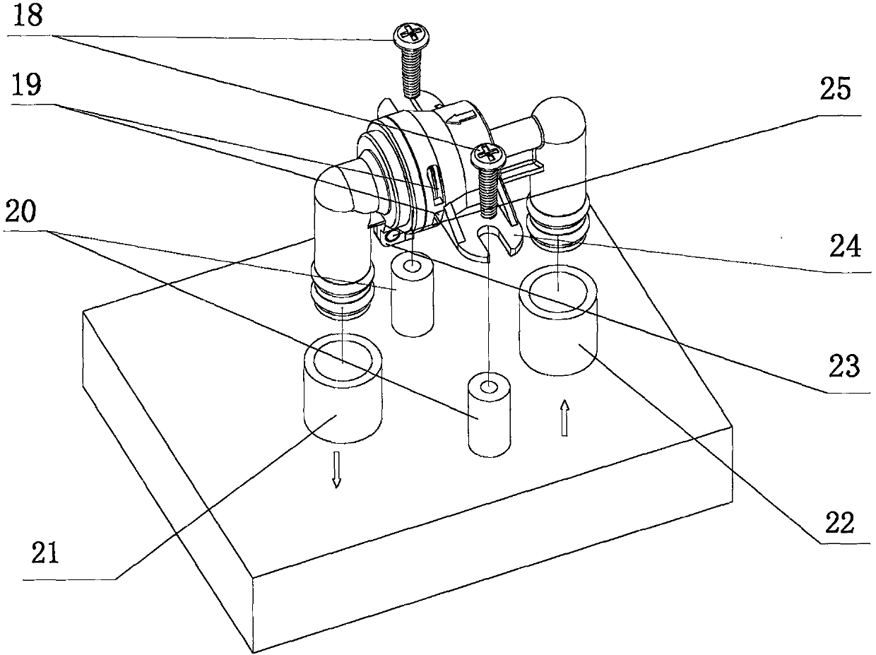
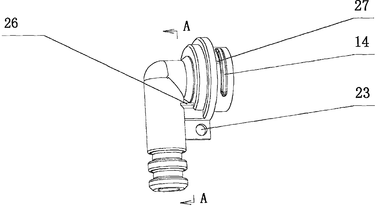
[0029] Specific implementation mode one: see Figure 1 to Figure 12 , a pressure reducing valve with a screw buckle without screws, mainly including a front cover 2, a valve core 5, a valve core "O" ring 4, a rubber plug 6, a piston 17, a piston "O" ring 7, a spring 3, The rear cover 8 is characterized in that the front cover 2 and the rear cover 8 are connected by screw snaps, and the design scheme does not need to be assembled with screws 53; the piston "O" ring 7 inside the pressure reducing valve is set on the outer cylindrical surface 12 of the piston, It forms a sealing fit with the back cover 8, and the valve core "O" ring 4 is sleeved on the outer cylindrical surface 16 of the valve core, and forms a sealing fit with the inner cylindrical surface of the water inlet end of the piston 17. The rubber plug 6 is installed on the piston 17, and the piston 17 is reciprocated between the front cover 2 and the rear cover 8 by compressing the spring 3. The water inlet and outle...

specific Embodiment approach 2

[0037] The second specific embodiment, this embodiment is a specific application example of the present invention, that is, the application on a common, non-U-shaped pressure reducing valve. see Figures 1 to 7 , see Figure 8 to Figure 9, a screwless screwless pressure reducing valve, mainly including a front cover 43, a valve core 42, a valve core "O" ring 41, a rubber plug 36, a piston 39, a piston "O" ring 37, a spring 40, The rear cover 35 is characterized in that the front cover 43 and the rear cover 35 are connected by a screw buckle, and no screw 55 is used for assembly; the piston "O" ring 37 inside the pressure reducing valve is sleeved on the outer cylindrical surface of the piston 39, It forms a sealing fit with the back cover 35, and the spool "O" ring 41 is sleeved on the spool 42, and forms a sealing fit with the inner cylindrical surface of the water inlet end of the piston 39. The rubber plug 36 is installed on the piston 39, and the piston 39 is between the...


PUM


Abstract

The invention discloses a spiral buckle type screw-free pressure reducing valve. The pressure reducing valve mainly comprises a front cover, a valve core, a valve core O-shaped ring, a rubber plug, apiston, a piston O-shaped ring, a spring and a rear cover and is characterized in that the design structure scheme that the front cover and the rear cover are connected through a spiral buckle and areassembled without screws is adopted. The pressure reducing valve has the advantages of being simple in structure, good in production process, high in assembly efficiency, good in pressure reduction performance, durable and reliable due to the adoption of the double O-shaped rings and capable of being widely applied to products of the water purifier and commercial water dispenser industry.

Description

technical field [0001] The invention relates to a screwless pressure reducing valve with a screw buckle and relates to the technical field of commercial water dispensers and household water purifiers in the water treatment industry. More specifically, it also relates to the application field of using pressure reducing valves on city tap water, domestic water supply systems and integrated waterway boards of water purifiers. Background technique [0002] The pressure reducing valve used on the existing integrated waterway board uses more screws to connect and fasten the front and rear valve body shells, such as Figure 11 The patent advance publication number shown in serial number 55: 2019112725546, the patent prior application number: 2018116310773, a special U-shaped pressure reducing valve for integrated waterway board uses as many as 4 screws. Because there is a spring inside the pressure reducing valve, the production process first needs to compress the spring to prevent...

Claims


Application Information

Patent Timeline
Patent Type & Authority Applications(China)
IPC IPC(8): F16K17/30F16K27/02
CPCF16K17/30F16K27/02
Inventor 樊响
Owner 樊响
Why Eureka
Try Eureka