
Soil body 3D displacement measuring device

A technology of displacement measurement and soil mass, which is applied in the direction of measuring device, electromagnetic measuring device, electric/magnetic solid deformation measurement, etc. It can solve the problem of poor accuracy and real-time performance, high difficulty, unification of layered displacement and deep displacement of soil The application of automated measurement and other issues to achieve the effect of automation

Pending Publication Date: 2020-07-24
SHANGHAI ZENITECH ELECTRONICS TECH DEV
View PDF0 Cites 14 Cited by
  • Summary
  • Abstract
  • Description
  • Claims
  • Application Information

AI Technical Summary

Problems solved by technology

[0011] 1) At present, it mainly relies on the manual magnetic ring sedimentation method, which has a large workload and no automated testing method;
[0012] 2) In the multi-point displacement meter method, the anchor head moving in the measurement hole is actually not directly connected to the surrounding soil layer, and the response to the displacement change of the soil layer must be sensed through the backfill soil (mortar, mud), which has poor accuracy and real-time performance. Especially in the early stage of installation, when the backfill is unstable;
[0013] 3) The installation of the multi-point displacement meter is complicated and difficult, and the installation and maintenance cost is too high;
[0014] To sum up, for the existing measurement methods and equipment for soil delamination displacement in soft soil, it is difficult to complete the measurement of soil delamination displacement in real time, accurately and stably, and there is no application of unified automatic measurement of delamination displacement and soil deep displacement

Method used


Image

  • Soil body 3D displacement measuring device
  • Soil body 3D displacement measuring device
  • Soil body 3D displacement measuring device

Examples


Embodiment Construction

[0032] Embodiments of the present application are described below through specific examples, and those skilled in the art can easily understand other advantages and effects of the present application from the content disclosed in this specification. The present application can also be implemented or applied through other different specific implementation modes, and various modifications or changes can be made to the details in this specification based on different viewpoints and applications without departing from the spirit of the present application. It should be noted that, in the case of no conflict, the following embodiments and features in the embodiments can be combined with each other.

[0033] It should be noted that the diagrams provided in the following embodiments are only schematically illustrating the basic idea of ​​the application, and only the components related to the application are shown in the diagrams rather than the number, shape and Dimensional drawing,...


PUM


Abstract

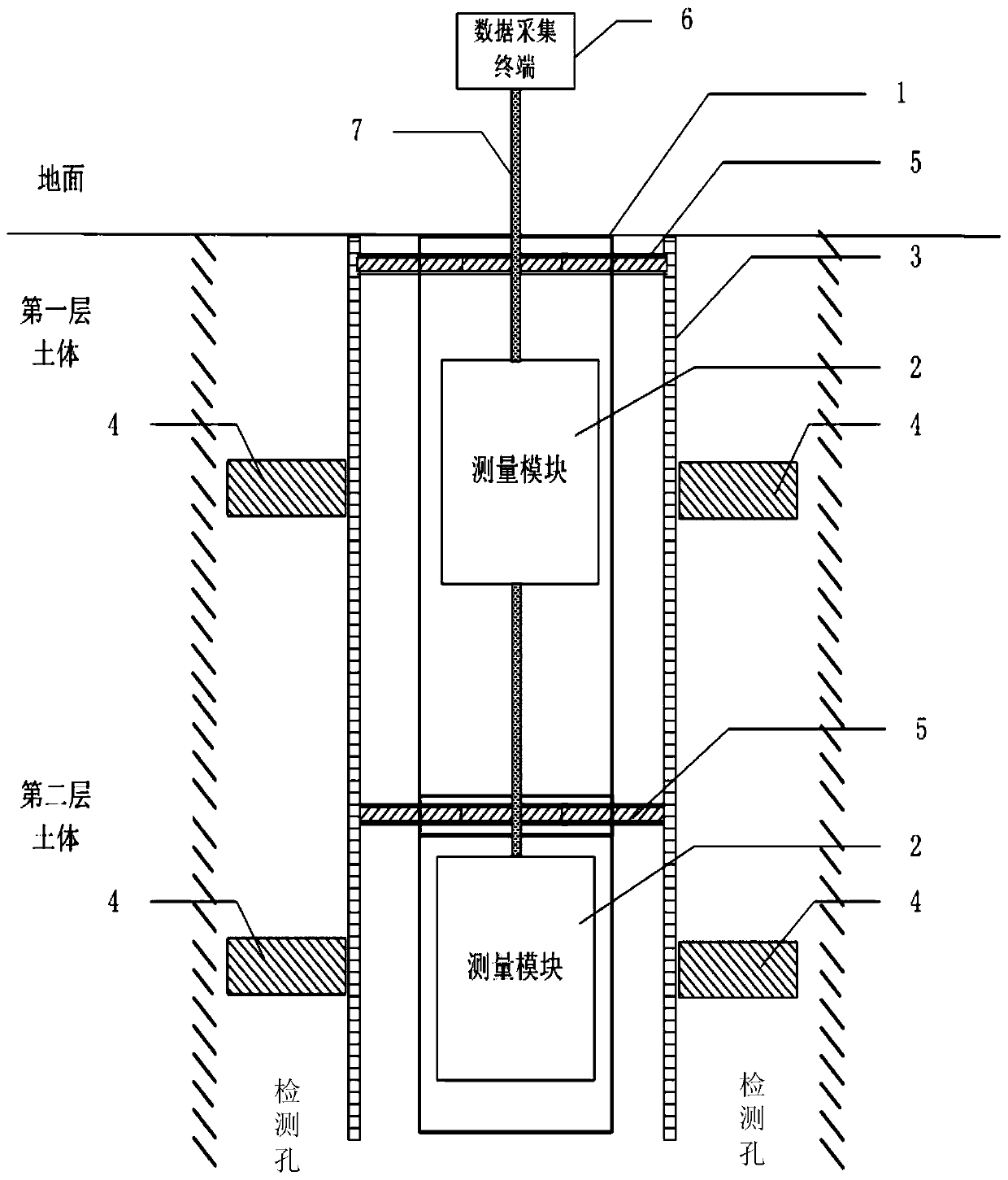
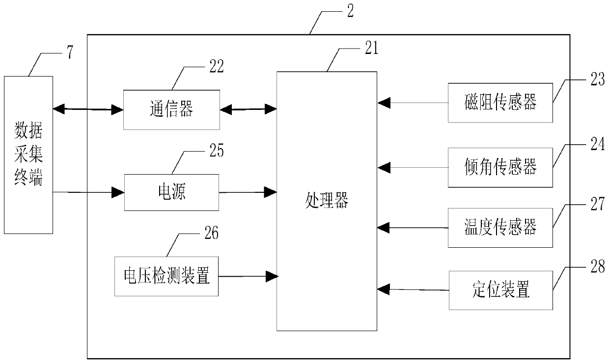
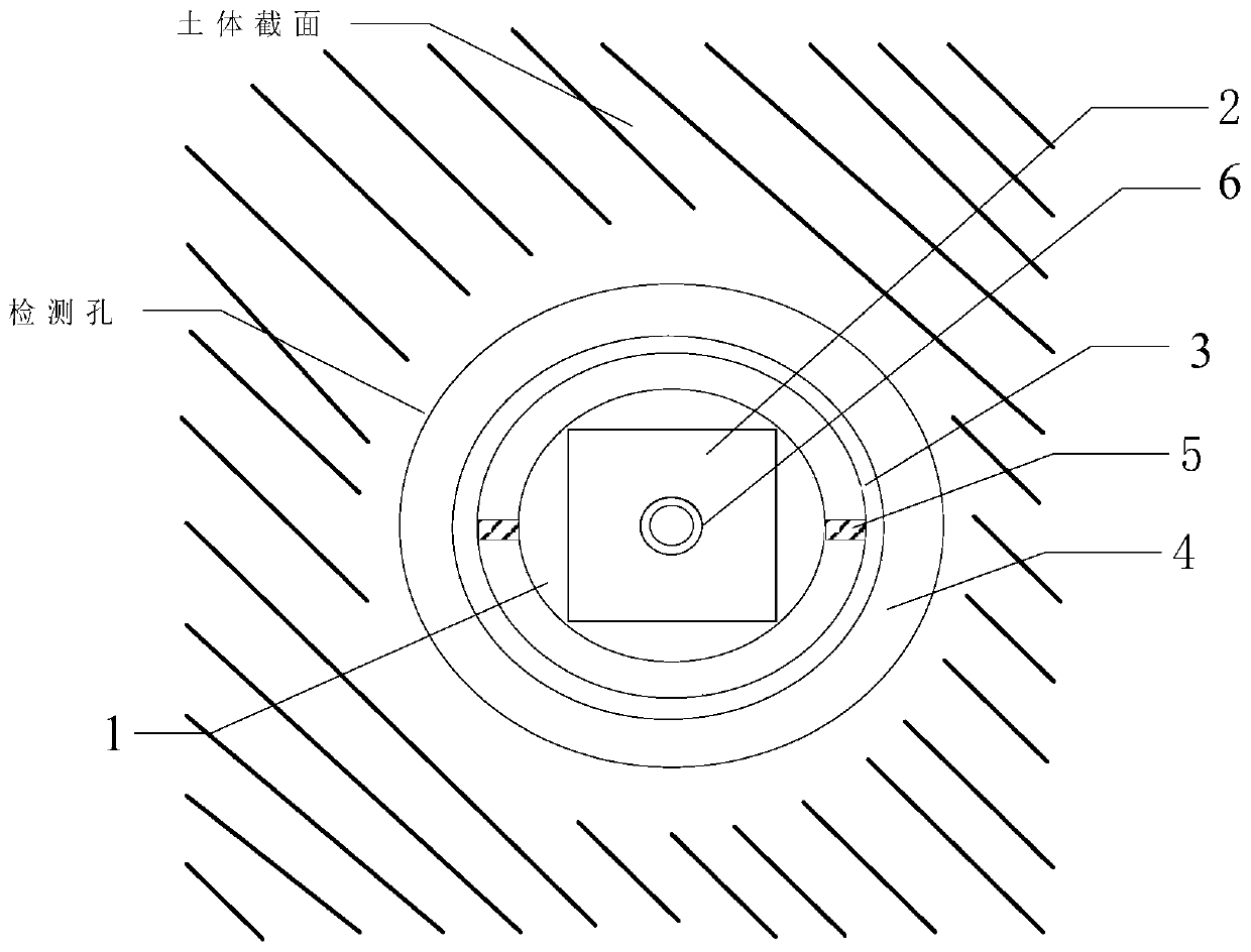
The invention provides a soil body 3D displacement measuring device. The device comprises at least one measuring rod, which is internally provided with one or more measuring modules; the device also comprises an inclinometer pipe buried in a soil body; each of measuring rods is suspended in the inclinometer pipe through a pin; a magnetic ring is fixedly arranged outside the inclinometer pipe; eachmeasuring module comprises a processor, a communicator, a magnetoresistive sensor and an inclination angle sensor; the processor is used for collecting displacement data and inclination angle data and transmitting the displacement data and the inclination angle data through the communicator; the measuring modules are connected in series to a data acquisition terminal through a power supply and acommunication cable; and the data acquisition terminal is used for supplying power to the measurement modules and uploading acquired data to the cloud. The soil body 3D displacement measuring device can continuously work, and deep soil body horizontal displacement measurement can be completed while real-time layered displacement measurement is achieved, so that the problems of ''slow detection, inaccurate detection and complex installation'' of existing soil body detection are solved, and automatic, real-time and continuous monitoring of internal displacement deformation of the soil body is achieved.

Description

technical field [0001] This application relates to the technical field of soil deformation information monitoring, in particular to a soil 3D displacement measurement device. Background technique [0002] The settlement and deformation of various buildings are closely related to the bearing soil. In order to ensure the safety of buildings, especially roads, bridges, subways, high-speed rails, dams, etc., the displacement of deep soil must be monitored. Horizontal displacement monitoring of deep soil such as mountain soil landslides, tailings pond deformation, dam deformation, and deep foundation pit deformation is one of the important monitoring items in the geological disaster monitoring system. At present, there are fixed inclinometers to solve this problem. [0003] Soft soil areas are mostly silt, silt clay and silt subclay, which generally have the characteristics of high water content, low water permeability and low strength, and must be treated during underground cons...

Claims


Application Information

Patent Timeline
Patent Type & Authority Applications(China)
IPC IPC(8): G01B7/02G01B7/16G01C5/00
CPCG01B7/02G01B7/18G01C5/00
Inventor 杨峰王喜超唐健清周海涛王金红何铁
Owner SHANGHAI ZENITECH ELECTRONICS TECH DEV
Learn More