Electrical system detection device and detection system
A detection device and electrical system technology, which is applied in the direction of measuring devices, measuring device shells, and measuring electronics, can solve the problems of inconvenient device carrying, inconvenient handling and movement, and bulky electrical detection devices, so as to achieve enhanced practicability and equipment detection. Precise, maneuverable results
- Summary
- Abstract
- Description
- Claims
- Application Information
AI Technical Summary
Problems solved by technology
Method used
Image
Examples
Embodiment 1
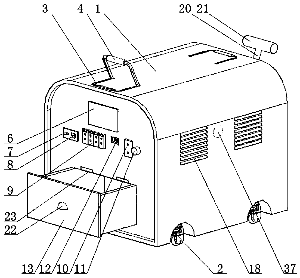
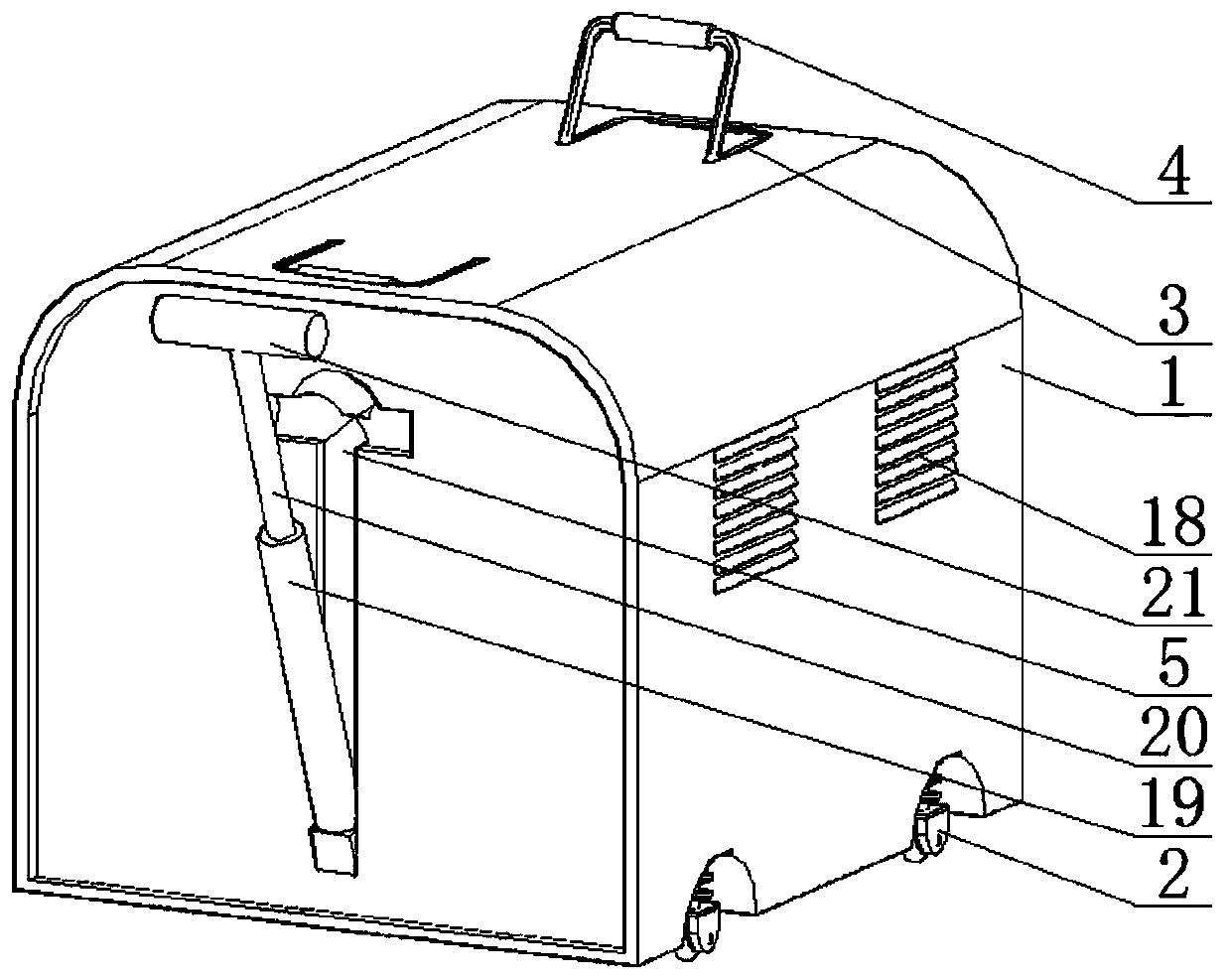
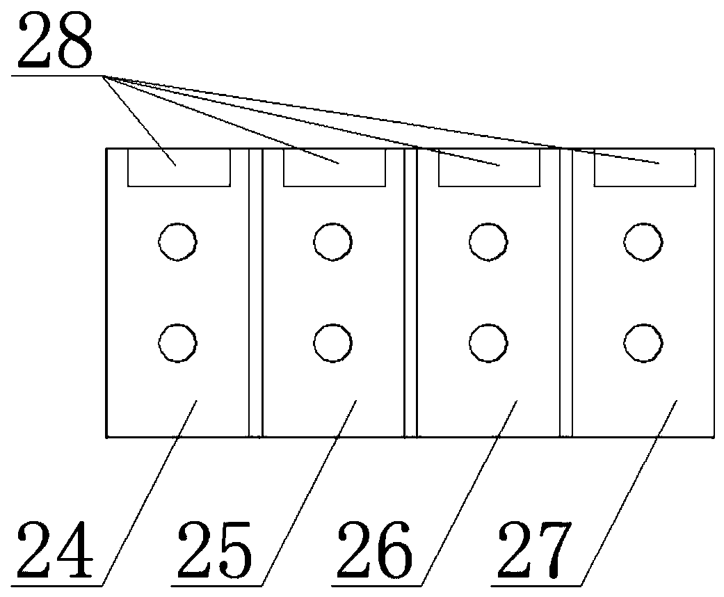
[0024] see Figure 1-6 , an electrical system detection device, comprising a detection case 1, two sets of moving rollers 2 for device movement are respectively fixedly installed on both sides of the bottom of the detection case 1, and two groups of handle mounting grooves 3 are symmetrically arranged on the upper end surface of the detection case 1, A handle 4 for device transportation is hinged in the handle installation groove 3, and the handle 4 can be fitted and connected in the handle installation groove 3, and a pull rod groove 5 is opened on the front end of the detection case 1, and the bottom hinge connection of the pull rod groove 5 is useful. The pull rod device that moves with the pull device is located on the upper part of the rear end surface of the detection chassis 1, and is respectively provided with a display screen 6 for displaying detection information, a switch button 7 for controlling the switch button 7, and a charging socket 8 for charging the storage b...
Embodiment 2
[0026] In an electrical system detection device of the present invention, please refer to Figure 5 , the mobile roller 2 includes an inner connecting pipe 14, a slide bar 15, a damping spring 16, and a universal wheel 17 with a foot brake. The two sides of the bottom of the detection cabinet 1 are respectively provided with wheel grooves, and the upper end of the inner connecting pipe 14 is fixedly connected to the top of the wheel groove. In the center, the lower end of the inner connecting pipe 14 is slidably connected with a slide bar 15, and the bottom end of the sliding bar 15 is fixedly connected with a universal wheel 17. The ends are respectively connected with the inner wall of the wheel groove and the upper end of the outer wheel in conflict, wherein the damping spring 16 is used to slow down the vibration when the device moves, thereby reducing the damage caused by the vibration to the detection system device.
[0027] The two sides of the system installation cavit...
Embodiment 3
[0033] see Figure 1-6 , a detection system of an electrical system detection device, comprising a detection system device, the detection system device comprising a circuit board 29, a multifunctional regulator 30, a current measuring instrument 31, a voltage measuring instrument 32, a main control chip 33, a signal receiver 34, Data analyzer 35, power adapter 36, alarm 37, multi-function regulator 30, current measuring instrument 31, voltage measuring instrument 32, main control chip 33, signal receiver 34, data analyzer 35, power adapter 36 Connected on the circuit board 29, the detection line interface row 9, the multi-function detection line interface, and the data transmission socket 12 are fixedly connected to one side of the circuit board 29 and are fitted and connected to the rear end surface of the detection case 1, and the switch button 7 and the charging socket are arranged. One end of the power adapter 36 is extended and fitted on the rear end surface of the detect...
PUM
 Abstract
Description
Claims
Application Information
 - R&D
- Intellectual Property
- Life Sciences
- Materials
- Tech Scout
- Unparalleled Data Quality
- Higher Quality Content
- 60% Fewer Hallucinations
Browse by: Latest US Patents, China's latest patents, Technical Efficacy Thesaurus, Application Domain, Technology Topic, Popular Technical Reports.
© 2025 PatSnap. All rights reserved.Legal|Privacy policy|Modern Slavery Act Transparency Statement|Sitemap|About US| Contact US: help@patsnap.com


