On-line monitoring system for power transmission line insulator flashover

A technology for transmission lines and monitoring systems, applied in signal transmission systems, circuit devices, battery circuit devices, etc., can solve problems such as short-term or long-term power outages, loss, and burnt insulators on the line, so as to solve power supply problems and facilitate The effect of real-time monitoring

Inactive Publication Date: 2020-07-24
南京电博机器人技术有限公司
View PDF4 Cites 1 Cited by
  • Summary
  • Abstract
  • Description
  • Claims
  • Application Information

AI Technical Summary

Problems solved by technology

[0002] The number of power outages caused by insulation faults in high-voltage transmission lines is high, and the insulators of transmission lines are the weak link in the insulation of high-voltage transmission lines. In the harsh environment of rain, humidity and dirt, flashover often occurs due to surface pollution or lightning strikes on the line. The flashover of the insulator will lead to short circuit grounding, which will not only burn out the insulator, but also cause the circuit breaker of the substation to trip. Short-term or long-term power outages will cause heavy losses. Therefore, the power department must always know when and where flashovers occur on the insulators of high-voltage transmission lines, so that the staff can repair and maintain the lines in time. For this reason, we Propose an on-line monitoring system for transmission line insulator flashover

Method used


Image

  • On-line monitoring system for power transmission line insulator flashover
  • On-line monitoring system for power transmission line insulator flashover

Examples


Embodiment Construction

[0014] In order to make the purpose, technical solutions and advantages of the embodiments of the present disclosure clearer, the technical solutions of the embodiments of the present disclosure will be clearly and completely described below in conjunction with the drawings of the embodiments of the present disclosure.

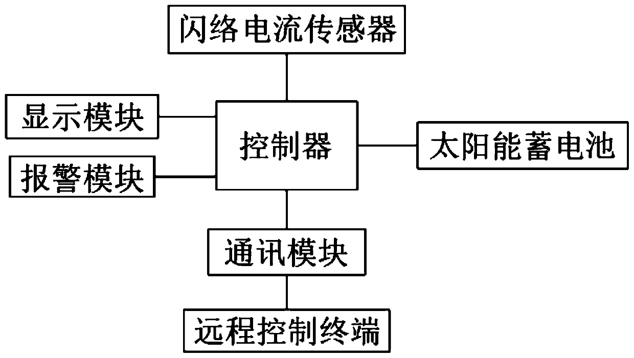
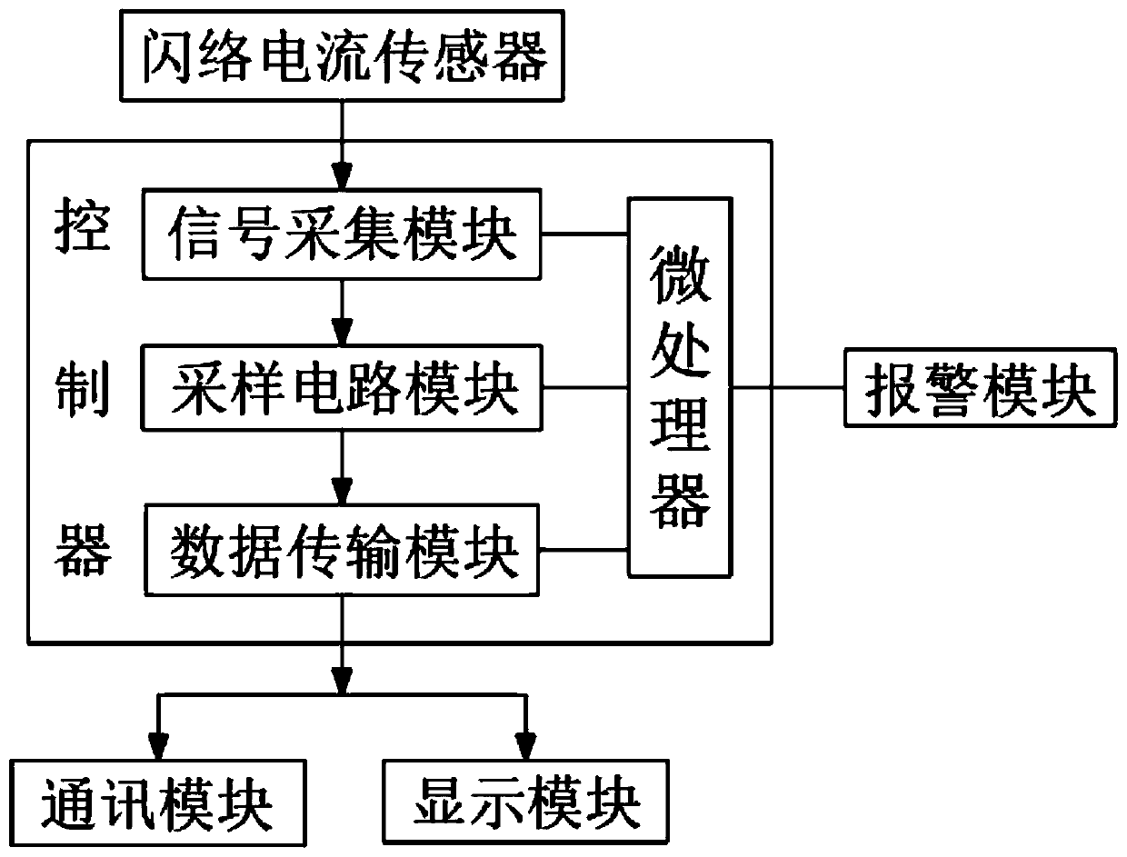
[0015] see Figure 1-2 , a transmission line insulator flashover online monitoring system, including a controller, a flashover current sensor, a communication module, a remote control terminal, a display module and an alarm module; the output of the flashover current sensor and the input of the controller electrical connection; the output end of the controller is electrically connected to the communication module, the display module and the alarm module; the output end of the communication module is wirelessly connected to the remote control terminal.

[0016] It also includes a solar battery, and the solar battery is electrically connected to the controller. ...


PUM


Abstract

The invention relates to the technical field of power transmission line monitoring, and discloses an online monitoring system for a power transmission line insulator flashover. The system comprises acontroller, a flashover current sensor, a communication module, a remote control terminal, a display module and an alarm module; the output end of the flashover current sensor is electrically connected with the input end of the controller; the output end of the controller is electrically connected with the communication module, the display module and the alarm module; and the output end of the communication module is wirelessly connected with the remote control terminal. According to the system, flashover signals of an insulator are collected by the flashover current sensor, the acquired signals are displayed and transmitted in real time through the controller, and the data information can also be wirelessly sent to the remote control terminal through the communication module, so that a worker can conveniently monitor flashover information in real time, an alarm signal is sent out, the worker can receive the alarm information at the first time, and the worker is reminded to repair a power transmission line in time.

Description

technical field [0001] The invention relates to the technical field of transmission line monitoring, in particular to an on-line monitoring system for transmission line insulator flashover. Background technique [0002] The number of power outages caused by insulation faults in high-voltage transmission lines is high, and the insulators of transmission lines are the weak link in the insulation of high-voltage transmission lines. In the harsh environment of rain, humidity and dirt, flashover often occurs due to surface pollution or lightning strikes on the line. The flashover of the insulator will lead to short circuit grounding, which will not only burn out the insulator, but also cause the circuit breaker of the substation to trip. Short-term or long-term power outages will cause heavy losses. Therefore, the power department must always know when and where flashovers occur on the insulators of high-voltage transmission lines, so that the staff can repair and maintain the li...

Claims


Application Information

Patent Timeline
Patent Type & Authority Applications(China)
IPC IPC(8): G01R31/12H02J7/35G08B21/18G08B21/24G08C17/02
CPCG01R31/1245H02J7/35G08B21/185G08B21/24G08C17/02
Inventor 朱和平
Owner 南京电博机器人技术有限公司
Why Eureka
Try Eureka