Optical display system, control method and display device

An optical display and display technology, applied in optics, optical components, nonlinear optics, etc., can solve the problems of difficult to meet the needs of thinning, inability to achieve ultra-thin, long optical path, etc.

Pending Publication Date: 2020-07-24
BOE TECH GRP CO LTD +1
View PDF13 Cites 13 Cited by
  • Summary
  • Abstract
  • Description
  • Claims
  • Application Information

AI Technical Summary

Problems solved by technology

The traditional VR optical system is limited by the focal length of the lens and the back focus, and the overall optical path is long, generally above 50mm, which cannot be ultra-thin, and it is difficult to meet the market's demand for thinning

Method used


Image

  • Optical display system, control method and display device
  • Optical display system, control method and display device
  • Optical display system, control method and display device

Examples


Embodiment 1

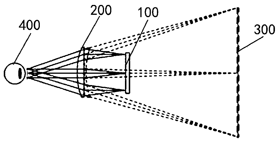
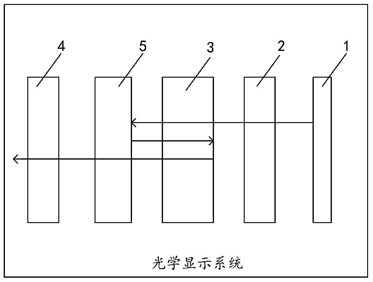
[0052] An embodiment of the present invention provides an optical display system, referring to figure 2 shown, including:

[0053]Display screen 1; the type of display screen is not limited here, for example, the display screen can be LCD (LiquidCrystal Display, liquid crystal display) display screen, OLED (Organic Light-Emitting Diode, organic light-emitting diode) display screen, Micro OLED Any one of micro-displays and Mini LED micro-displays; it can also be a DLP (Digital Light Processing, digital light processing) display; it can also be an LCOS (Liquid Crystal on Silicon, liquid crystal on silicon) display, etc. In addition, the display screen may be a flexible screen or a rigid screen (that is, a non-flexible screen). In practical applications, it can be selected according to user requirements.

[0054] The first light splitting unit 2 is arranged on the display side of the display screen 1; it is configured to transmit the first type of polarized light and block the...

Embodiment 2

[0103] An embodiment of the present invention provides a display device, including the optical display system provided in Embodiment 1.

[0104] The display device may be a VR (Virtual Reality, virtual reality) display device, or may be another display device including a folding optical system. The display device has the characteristics of light and thin, short focus and good display effect.

Embodiment 3

[0106] An embodiment of the present invention provides a control method for an optical display system, which can be applied to such as Figure 4 In the shown optical display system, the control method includes:

[0107] S01. In a first period of time, input a first focal plane image signal to a display screen.

[0108] S02. Control the display screen to display the first focal plane image; the light emitted by the display screen sequentially passes through the first light splitting unit and the first imaging unit to form an enlarged image corresponding to the first focal length.

[0109] The aforementioned first focal length is the focal length included in the optical display system. Focal length, also known as focal length, is a measure of the concentration or divergence of light in an optical system, and refers to the distance from the center of the lens to the focus of light concentration.

[0110] S03. Control the phase modulation unit to have a phase modulation value of...


PUM


Abstract

The invention provides an optical display system, a control method and a display device, relates to the technical field of display. The market requirement for thinning can be met. The optical displaysystem comprises a display screen, a first light splitting unit, a first imaging unit, a second light splitting unit and a phase modulation unit. The first light splitting unit is arranged on the display side of the display screen, and the light emitted by the display screen is converted into first polarized light after passing through the first light splitting unit. The first imaging unit is arranged on the light emission side of the first light splitting unit, and comprises a light splitting film which is arranged on the light incident surface of the first imaging unit. The second light splitting unit is arranged on the light emission side of the first imaging unit and can be configured to transmit the first polarized light and reflect second polarized light. The phase modulation unit isat least arranged on a light path from the first imaging unit to the second light splitting unit. The first polarized light transmitted by the first light splitting unit is repeatedly turned back between the first imaging unit and the second light splitting unit and then is emitted from the light emission side of the second light splitting unit. The method is suitable for manufacturing the optical display system.

Description

technical field [0001] The invention relates to the field of display technology, in particular to an optical display system, a control method, and a display device. Background technique [0002] The structure and optical path used in virtual reality technology (Virtual Reality, VR) are as follows: figure 1 As shown, the image source generated by the display 100 is refracted by the traditional optical lens 200 and becomes a magnified virtual image 300 to facilitate observation by the human eye 400 . The traditional VR optical system is limited by the focal length of the lens and the back focus, and the overall optical path is long, generally above 50mm, which cannot be ultra-thin, and it is difficult to meet the market's demand for thinning. Contents of the invention [0003] Embodiments of the present invention provide an optical display system, a control method, and a display device, and the optical display system can meet the market demand for thinning. [0004] In ord...

Claims


Application Information

Patent Timeline
Patent Type & Authority Applications(China)
IPC IPC(8): G02B27/01G02B27/28
CPCG02B27/0172G02B27/283G02B27/286G02B27/0101G02B5/3058G02B27/0018G02B2027/0185G02B2027/0134G02B30/25G02F1/13731
Inventor 王晨如董瑞君栗可武玉龙陈丽莉张浩曲峰
Owner BOE TECH GRP CO LTD
Why Eureka
Try Eureka