VCM motor base structure, VCM motor, photographic device and electronic product

A motor and bottom surface technology, applied in the field of photographic equipment, can solve the problems of cracking of the dustproof ring, affecting the performance and appearance of the motor, and narrow width of the dustproof ring, so as to avoid cracking, increase the contact fixing area, and improve the aesthetics.

Pending Publication Date: 2020-07-24
NEW SHICOH MOTOR CO LTD
View PDF0 Cites 1 Cited by
  • Summary
  • Abstract
  • Description
  • Claims
  • Application Information

AI Technical Summary

Problems solved by technology

[0003] The existing base is generally provided with a dust-proof ring, the dust-proof ring is generally high in height, protruding from the bottom surface of the base, and the width of the dust-proof ring is narrow
After the injection molding is completed, due to the influence of the height of the dust-proof ring, the position of the dust-proof ring corresponding to the weld line cracks, which affects the performance and appearance of the motor

Method used


Image

  • VCM motor base structure, VCM motor, photographic device and electronic product
  • VCM motor base structure, VCM motor, photographic device and electronic product
  • VCM motor base structure, VCM motor, photographic device and electronic product

Examples


Embodiment 1

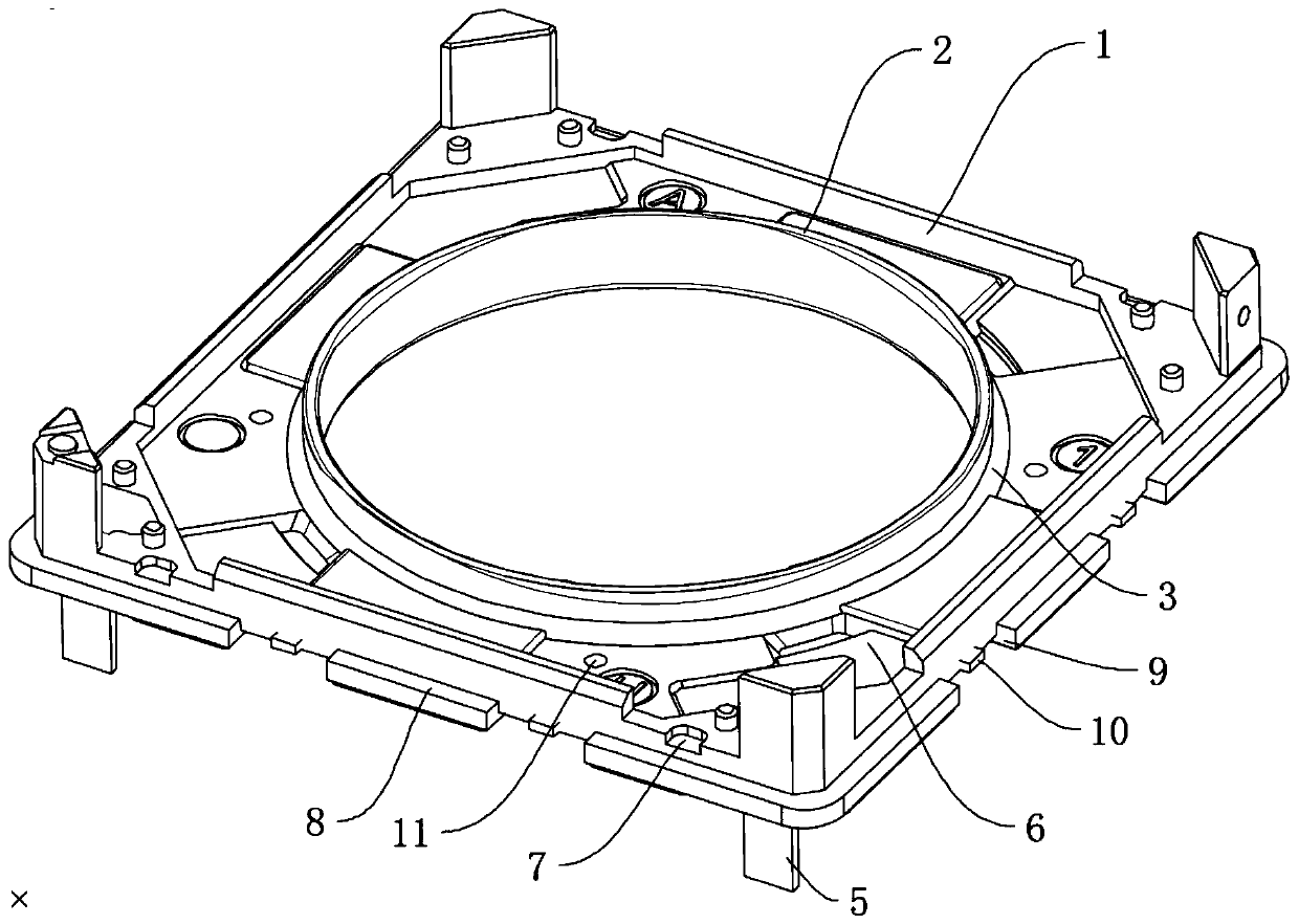
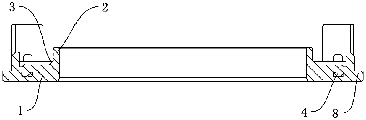
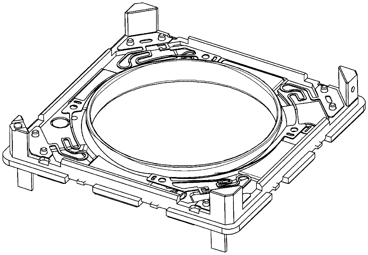
[0029] Example 1 as Figure 1 to Figure 3 As shown, a VCM motor base structure proposed by the present invention includes a base body 1, the base body 1 is provided with a dust-proof ring 2, the dust-proof ring 2 is higher than the bottom surface of the base body 1, and the base body A C corner block 3 is integrally formed at the angle between the bottom surface of 1 and the side wall of the dustproof ring 2, and the C corner block 3 is annularly arranged at the angle between the bottom surface of the base body 1 and the side wall of the dustproof ring 2 position, and the position of the welding line of the base body 1 is located at the position of the C corner block 3, the metal reinforcement rib 4 is injected into the base body 1, the lower end surface of the base body 1 is provided with a connecting terminal 5, and the VCM The lower spring in the motor is electrically connected to the connecting terminal 5 . The connection strength of the dust-proof ring 2 is effectively i...

Embodiment 2

[0033] Embodiment 2, a VCM motor base structure, differs from Embodiment 1 in that: in this embodiment, the C corner block 3 is arranged in several sections between the bottom surface of the base body 1 and the side wall of the dustproof ring 2 corner position, and the welding line position of the base body 1 is located at the position of the C corner block 3 .

Embodiment 3

[0034] Embodiment 3, a kind of VCM motor, such as Figure 4 to Figure 7 As mentioned above, there is a VCM motor base structure described in Embodiment 1 or Embodiment 2, including a lower spring 12 , an upper spring 13 , a carrier 14 , a magnet 15 , and a housing 16 .

[0035] The upper spring 13 includes an outer ring 17 fixedly connected to the bottom surface of the housing 16, an inner ring 18 fixedly connected to the carrier 14, and a cantilever 19 arranged between the outer ring 17 and the inner ring 18. The shell 16 and the magnet 15 clamp and fix the outer ring 17, the cantilever 19 is set to four, and the four cantilever 19 are respectively arranged at the four corners of the base body 1, and one end of the cantilever 19 is connected to the inner ring 18 , the other end is connected to the outer ring 17, and the connecting end of the announcement and the inner ring 18 is located at the middle section of the base body 1, and the connecting end of the cantilever 19 and ...


PUM


Abstract

The invention discloses a VCM motor base structure, a VCM motor, a photographic device and an electronic product. The technical scheme is characterized in that the VCM motor base structure comprises abase body, which is provided with a dustproof ring, wherein the dustproof ring is higher than the bottom surface of the base body, a C-angle block is integrally formed at the included angle positionbetween the bottom face of the base body and the side wall of the dustproof ring, the C-angle block is arranged at the included angle position between the bottom surface of the base body and the sidewall of the dustproof ring in a plurality of sections or in a ring shape, the welding line of the base body is located at the position where the C-angle block is located, a metal reinforcing rib is arranged in the base body in an injection molding mode, a connecting terminal is arranged on the lower end face of the base body, and a lower spring in a VCM motor is electrically connected with the connecting terminal. According to the invention, the C angle is added between the dustproof ring and the bottom surface of the base, so that the joint line of the motor base can be prevented from cracking, and the strength of the base is effectively improved.

Description

technical field [0001] The invention relates to the field of photographic equipment, in particular to a base structure of a VCM motor, a VCM motor, a photographic device and electronic products. Background technique [0002] Existing VCM motor mainly includes, base, carrier, upper spring, lower spring, magnet, coil, shell and so on. The existing base is generally formed by injection molding, and when the base is injected, the base will generate a welding line (mold line). The main reason for the weld line is that when several glue melts meet together in the cavity, the fusion is not completed at the intersection, and they cannot be fused with each other to form a fusion mark. [0003] However, the existing base is generally provided with a dust-proof ring. The dust-proof ring is generally high in height and protrudes on the bottom surface of the base, and the width of the dust-proof ring is narrow. After the injection molding is completed, due to the influence of the heigh...

Claims


Application Information

Patent Timeline
Patent Type & Authority Applications(China)
IPC IPC(8): H02K41/035
CPCH02K41/0354
Inventor 吴攀德
Owner NEW SHICOH MOTOR CO LTD
Why Eureka
Try Eureka