Method for testing eyes and vision testing system

A vision detection, eye technology, applied in eye examination, eye testing equipment, application, etc., can solve cycloplegia, discomfort, time-consuming and other problems

Pending Publication Date: 2020-07-28
OCULUS OPTIKGERATE GMBH
View PDF1 Cites 2 Cited by
  • Summary
  • Abstract
  • Description
  • Claims
  • Application Information

AI Technical Summary

Problems solved by technology

To rule this out, the ciliary muscle may be paralyzed by medication (cycloplegia), however, this is time consuming and uncomfortable for the person being tested

Method used


Image

  • Method for testing eyes and vision testing system

Examples


Embodiment Construction

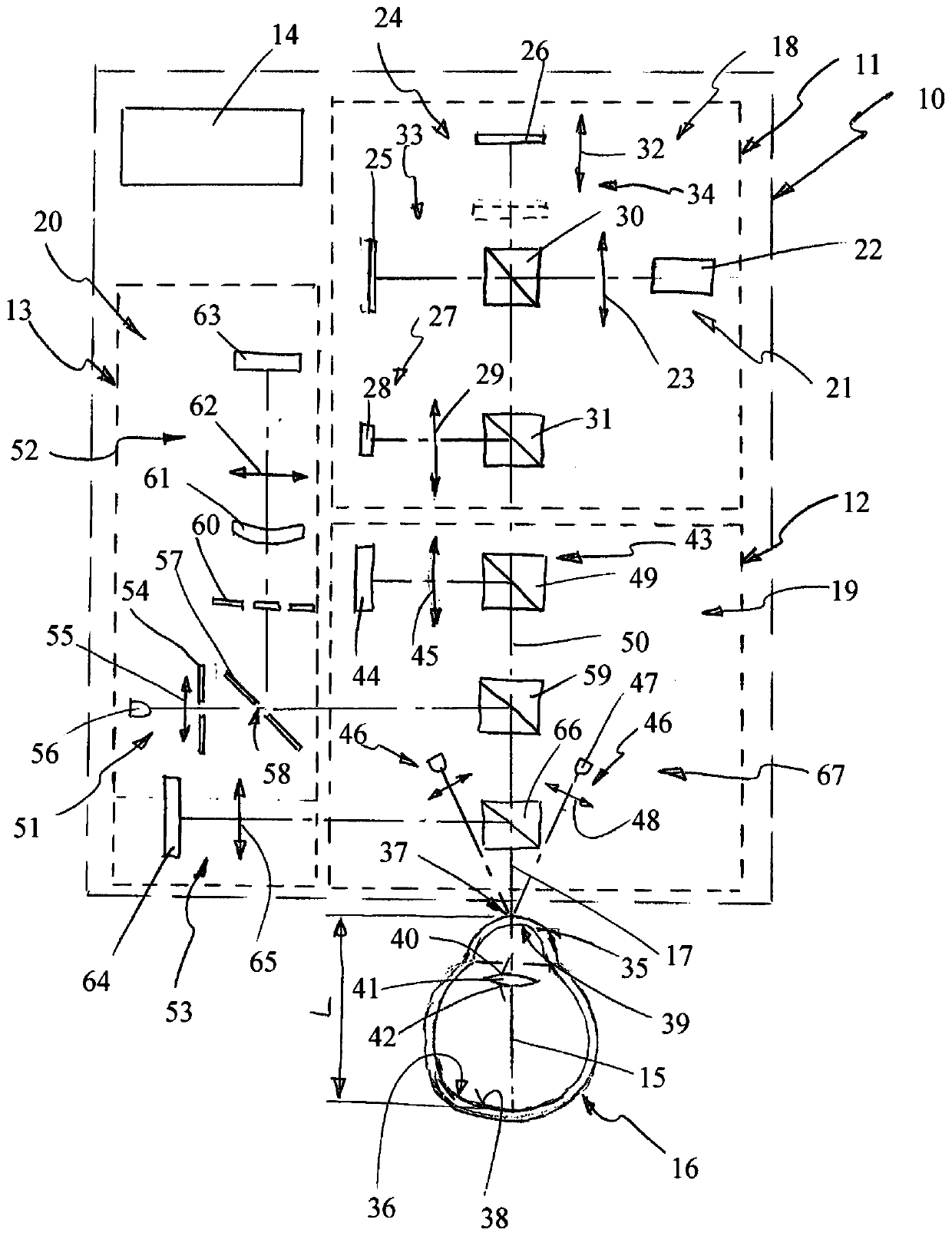
[0032] The drawing shows a schematic diagram of the configuration of a vision detection system 10 , which includes a first interferometric measurement device 11 , a second profile measurement device 12 , a third diopter measurement device 13 and a processing device 14 . Vision testing system 10 is arranged relative to visual axis 15 or optical axis of eye 16 to be examined such that visual axis 15 corresponds to measurement axis 17 of vision testing system 10 . The first interferometric means 11 is realized by a partially coherent interferometer 18 , the second topography measuring means 12 is realized by a keratometer 19 , and the third diopter measuring means 13 is realized by an automatic refractometer 20 .

[0033] The interferometer 18 generally passes through a laser device 21 having a laser light source 22 and a lens device 23, a mirror device 24 having a first mirror 25 and a second mirror 26, a detector device 27 having a detector 28 and a lens device 29, and a second ...


PUM


Abstract

The invention relates to a method for testing the eyes of a test person with the aid of a vision testing system (10) as well as vision testing system, comprising a first measuring device (12), a second topographic measuring device (12), a third refractive measuring device (13) and a processing means (14), an axial length (L) of an eye (16) of the test person being measured with the aid of the first measuring device, a curvature of the cornea (35) of the eye being measured with the aid of the second measuring device, a refractive property of the eye being measured with the aid of the third measuring device, a measurement simultaneously being carried out with the first, second and third measuring device at the eye, measurement data of the measurements of the first, second and third measuringdevice being processed with the aid of the processing means, the processing means presenting a database with normal data, a comparison of the measurement data with the normal data being carried out and a result of the comparison being issued by means of the processing means.

Description

technical field [0001] The invention relates to a method for testing the eyes of a person under test with the features of claim 1 and to a vision testing system with the features of claim 11 . Background technique [0002] Diopter measuring devices are well known and are commonly used to determine the diopter value of a person's eye. This diopter value can be used to assess the optical refractive error of the eye. A common form of refractive error is myopia in which the focal plane is located in front of the retina, resulting in a blurred visual impression. There are differences between the different forms of myopia. In so-called axial myopia, the axial length of the eye increases. In the case of refractive myopia, the refractive power of the refractive part of the eye, such as the cornea or lens, increases. For example, an increase in refractive power may be due to an increase in the curvature of a refractive surface such as the cornea. The refractive power of the lens...

Claims


Application Information

Patent Timeline
Patent Type & Authority Applications(China)
IPC IPC(8): A61B3/103A61B3/10
CPCA61B3/103A61B3/1005A61B3/10A61B3/102A61B3/145A61B5/7275A61B3/0025A61B3/0041A61B3/0091A61B3/107A61B3/1225A61B3/14A61B3/18A61B8/10
Inventor 安德烈亚斯·施泰因米勒
Owner OCULUS OPTIKGERATE GMBH
Why Eureka
Try Eureka