
Groove drainage tube capable of flushing

A drainage pipe and groove technology is applied in the field of flushable groove drainage pipes, which can solve the problems of inability to realize water injection and small diameter of water passing through, and achieve the effects of improving drainage effect, solving clogging problem, and stable and feasible structure.

Pending Publication Date: 2020-07-28
CHONGQING UNIV CANCER HOSPITAL
View PDF6 Cites 5 Cited by
  • Summary
  • Abstract
  • Description
  • Claims
  • Application Information

AI Technical Summary

Problems solved by technology

However, in actual production, due to the very small diameter of the groove drainage tube itself, whether it is to open a slender infusion cavity in the groove or to manufacture a slender capillary, the current technology is difficult to achieve. Even if it can be produced, water injection cannot be realized due to the extremely small diameter of the water.

Method used


Image

  • Groove drainage tube capable of flushing
  • Groove drainage tube capable of flushing
  • Groove drainage tube capable of flushing

Examples


Embodiment 1

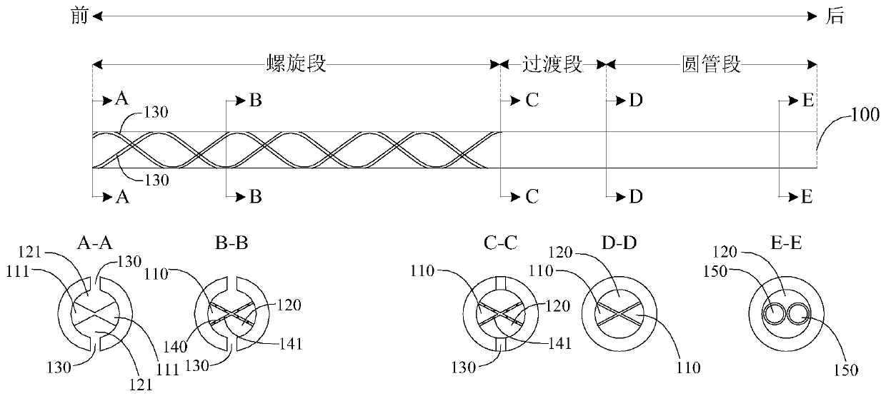
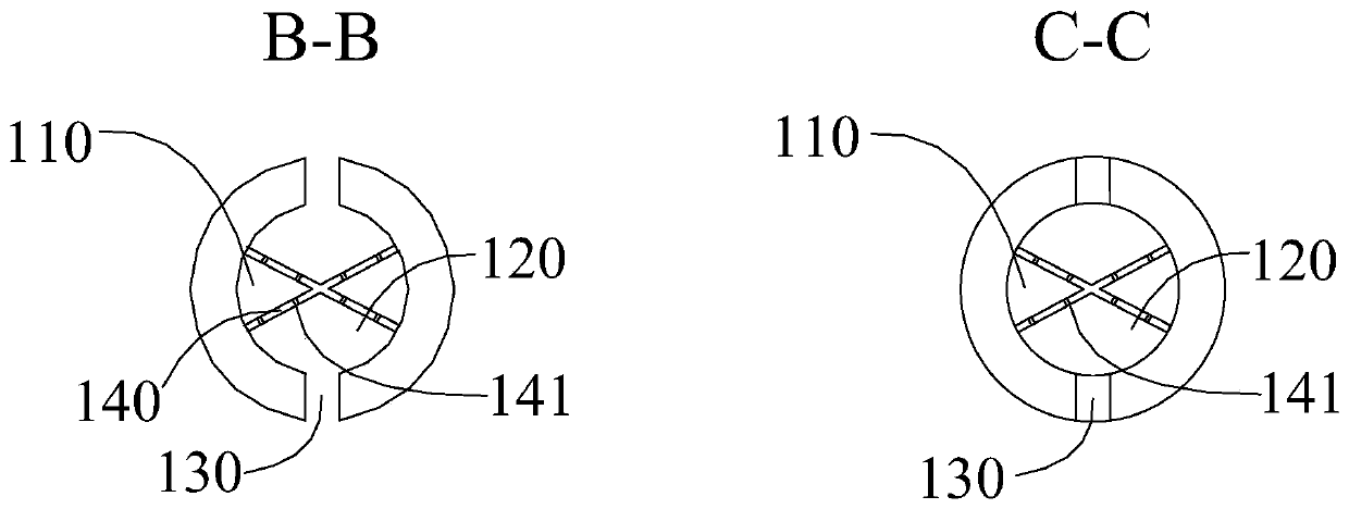
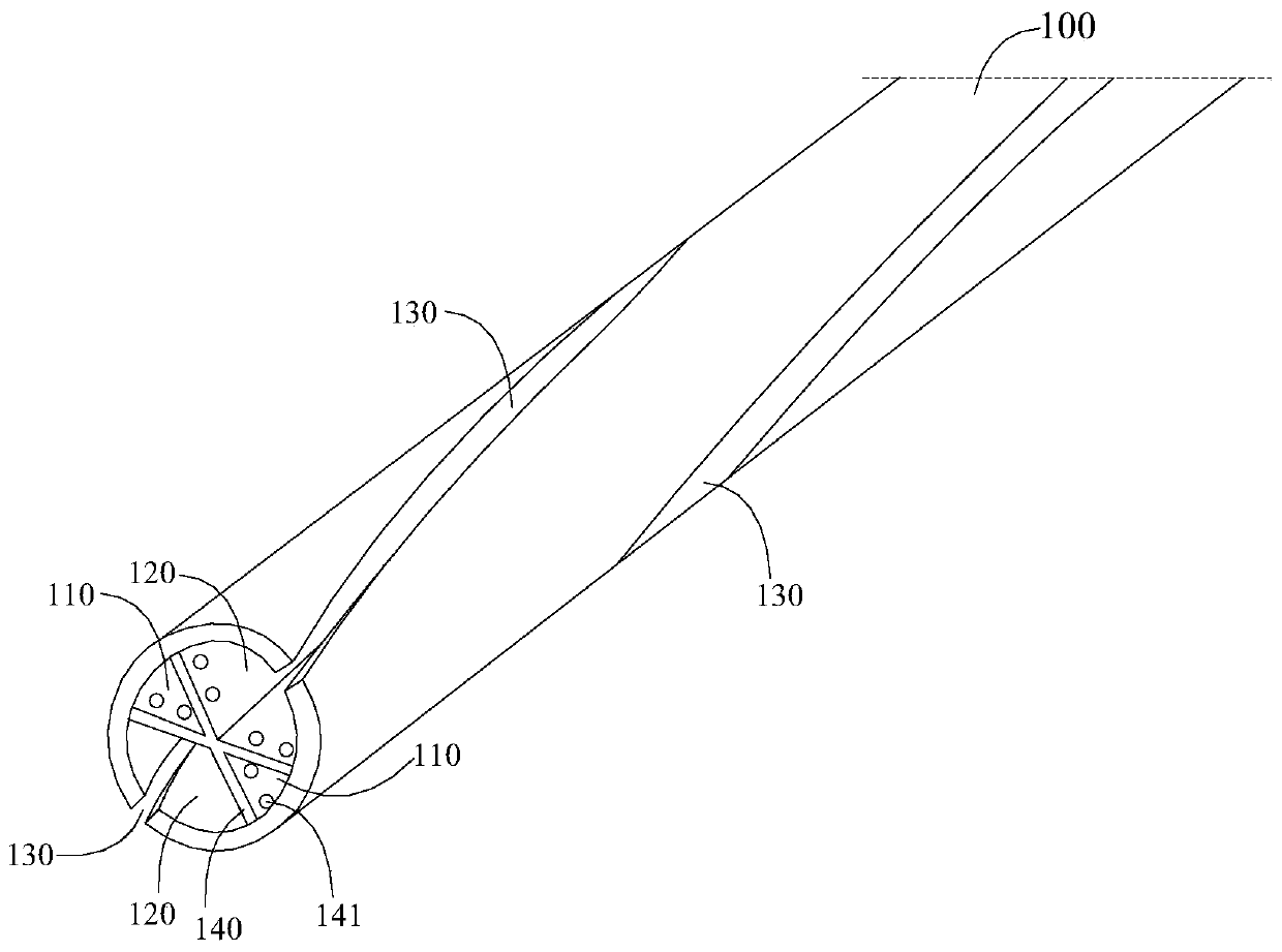
[0038] Example 1, please refer to Figure 1-3 , four lumens are opened in the drainage tube body 100 .

[0039] Specifically, as shown in the sectional views "B-B", "C-C", and "D-D", the cross section of the cavity wall 140 is X-shaped, two of which are used as the water injection cavity 110, and the other two are used as the drainage cavity 120, the water injection chamber 110 and the drainage chamber 120 are spaced apart from each other.

[0040] Optionally, the cross-sectional area of ​​the water injection chamber 110 is smaller than the cross-sectional area of ​​the drainage chamber 120, in order to reduce the occupation of the space of the drainage chamber 120 and facilitate the suction of human tissue fluid.

[0041] In this embodiment, as shown in the sectional view "A-A", the front end 111 of the water injection chamber is closed, and the front end 121 of the drainage chamber is open. Wherein, the front end 111 of the water injection chamber is closed, so that the wa...

Embodiment 2

[0045] Example 2, please refer to Figure 4 , 5 , three lumens are opened in the drainage tube body 100 .

[0046] Specifically, as shown in the sectional views "B-B", "C-C", and "D-D", the cross section of the chamber wall 140 is Y-shaped, one of which is used as the water injection chamber 110, and the other two chambers are used as the drainage chamber 120 , the water injection chamber 110 and the drainage chamber 120 are spaced apart from each other.

[0047] Compared with Embodiment 1, since there is only one water injection chamber 110 and two drainage chambers 120, the area of ​​the water injection chamber 110 in this embodiment will be smaller than the area of ​​the drainage chamber 120, greatly reducing the occupation of the space of the drainage chamber 120, It is more conducive to the suction of human tissue fluid.

[0048] In this embodiment, as shown in the sectional view "A-A", the front end 111 of the water injection chamber is closed, and the front end 121 o...


PUM


Abstract

The present invention discloses a groove drainage tube capable of flushing. The groove drainage tube capable of flushing comprises a drainage tube body, at least three cavity channels are axially arranged in the drainage tube body, at least one cavity channel is used as a water injection cavity, at least two cavity channels are used as drainage cavities, grooves are radially formed in the drainagecavities, wherein the drainage cavities and the water injection cavity are arranged at intervals through cavity walls; a plurality of flushing holes are formed in the cavity walls in a penetrating way; the drainage tube body comprises a spiral section arranged at a front part; and in the spiral section, the drainage cavities, the water injection cavity and the grooves all spirally extend along anaxial direction. The cavity channel of an inner part of the drainage tube body is used as the water injection cavity, the rest cavity channels are still used as the drainage cavities, besides, the drainage cavities and the water injection cavity are arranged at intervals through the cavity walls, besides, the flushing holes are formed in the cavity walls, after water is injected into the water injection cavity, water flows into the drainage cavities through the flushing holes to flush the grooves in the drainage cavities, so that a problem of blockage is solved.

Description

technical field [0001] The invention relates to the field of medical instruments, in particular to a flushable groove drainage tube. Background technique [0002] Grooved drainage tube is a special drainage tube used in abdominal cavity and thoracic drainage. Compared with ordinary drainage tubes, there are multiple axially extending grooves formed in the front section, which is more conducive to the immersion of human tissue fluid, thereby improving drainage efficiency. . However, during use, tissue debris, physiological residues and blood clots in the human tissue fluid are likely to block the groove and the drainage cavity under the groove, affecting the drainage effect. [0003] In the prior art, the patent with publication number CN205867284U proposes a solution for flushing and anti-blocking by using an infusion cavity or capillary embedded in a groove. However, in actual production, due to the very small diameter of the groove drainage tube itself, whether it is to ...

Claims


Application Information

Patent Timeline
IPC IPC(8): A61M1/00A61M25/00
CPCA61M1/0023A61M25/0043A61M25/0032A61M2025/0019A61M2025/0037A61M2025/006A61M1/83A61M1/85
Inventor 张希沈艾罗小军刘文彬
Owner CHONGQING UNIV CANCER HOSPITAL
Learn More