
Novel blanking die waste cut-off tool structure

A waste material cutting and blanking die technology, which is applied in transportation and packaging, vehicle parts, etc., can solve the problems of increasing the length of the die, affecting the production efficiency, and crushing the working surface of the die, so as to avoid iron filings, improve product quality and work efficiency effect

Inactive Publication Date: 2020-07-28
柳州宝钢汽车零部件有限公司
View PDF9 Cites 0 Cited by
  • Summary
  • Abstract
  • Description
  • Claims
  • Application Information

AI Technical Summary

Problems solved by technology

The blanking die is to use the stamping of the upper and lower dies to cut and separate the sheet material along the closed contour line, and use the material within the contour line as a die for blanking parts. During the blanking process, the material outside the contour line is an invalid sheet material. It is waste, which needs to be removed from the mold, and with the increasing size of auto parts and the requirements of production efficiency, it is usually required that the waste cutting knife can divide the waste into two parts or into multiple parts, and the mold is required to be in one Otherwise, the length of the mold will be increased, which will increase the cost of the mold and the size requirements of the machine. However, when it is completed within one step, there will usually be secondary shearing at the intersection of the blanking part and the scrap, resulting in iron Chips, these iron filings brought into the mold will cause crushing on the working surface of the mold, and also cause convex defects on the surface of the stamping part, making the workpiece need to be repaired, affecting production efficiency and increasing production costs

Method used


Image

  • Novel blanking die waste cut-off tool structure
  • Novel blanking die waste cut-off tool structure

Examples


Embodiment Construction

[0010] The present invention will be described in detail below in conjunction with the accompanying drawings and embodiments.

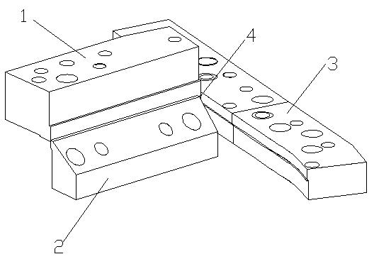
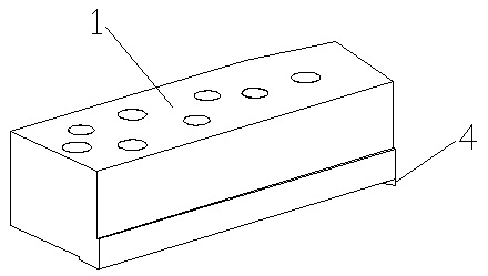
[0011] like figure 1 , figure 2 As shown, a novel blanking die waste material cutting knife structure of the present invention comprises a waste material upper mold knife block 1, a waste material lower mold knife block 2 and a blanking knife block 3, and the waste material upper mold knife block 1 is arranged on a waste material lower mold knife block Above 2, there is a lengthwise blade and a widthwise blade on the scrap upper mold cutter block 1, and the lengthwise blade matches the blade of the waste lower mold cutter block 2; the blanking cutter block 3 is arranged on the side of the waste lower mold cutter block 2 , the blade of the blanking knife block 3 matches the blade in the width direction on the waste upper mold knife block 1, and the intersection of the length direction blade and the width direction blade of the waste material upper mo...


PUM


Abstract

The invention discloses a novel blanking die waste cut-off tool structure. The novel blanking die waste cut-off tool structure comprises a waste upper die tool block, a waste lower die tool block anda blanking tool block, wherein the waste upper die tool block is provided with a length-direction cutting edge and a width-direction cutting edge; the length-direction cutting edge is matched with a cutting edge of the waste lower die tool block; the blanking tool block is arranged on the side edge of the waste lower die tool block; a cutting edge of the blanking tool block is matched with the width-direction cutting edge on the waste upper die tool block; a pointed cone-shaped cutting edge protruding downwards is arranged at the intersection of the length-direction cutting edge and the width-direction cutting edge of the waste upper die tool block; and a space for the pointed cone-shaped cutting edge to descend is arranged between the waste lower die tool block and the blanking tool block. By the adoption of the novel blanking die waste cut-off tool structure, scrap iron can be avoided, the die repairing frequency is reduced, the production efficiency is improved, and the quality of ablanking piece product is improved.

Description

technical field [0001] The invention relates to the technical field of molds for manufacturing automobile parts, in particular to a novel waste material cutting knife structure for a blanking mold. Background technique [0002] A variety of molds are used in the manufacturing process of automobile parts, and the blanking mold is one of them. The blanking die is to use the stamping of the upper and lower dies to cut and separate the sheet material along the closed contour line, and use the material within the contour line as a die for blanking parts. During the blanking process, the material outside the contour line is an invalid sheet material. It is waste, which needs to be removed from the mold, and with the increasing size of auto parts and the requirements of production efficiency, it is usually required that the waste cutting knife can divide the waste into two parts or into multiple parts, and the mold is required to be in one Otherwise, the length of the mold will be...

Claims


Application Information

Patent Timeline
Patent Type & Authority Applications(China)
IPC IPC(8): B21D28/14B21D53/88
CPCB21D28/14B21D53/88
Inventor 田景宇潘柳东李耀艺叶军韦斌
Owner 柳州宝钢汽车零部件有限公司
Learn More