Eureka AIR delivers breakthrough ideas for toughest innovation challenges, trusted by R&D personnel around the world.

Rapid demolding device for wear-resistant casting

A demolding device and demolding technology, applied in the field of wear-resistant castings, can solve the problems of inconvenient reuse, low efficiency, damage to the outer plate, etc., and achieve the effects of avoiding manual cleaning, facilitating the concentration of conveying, and improving the demoulding efficiency.

Inactive Publication Date: 2020-07-28
安徽省安工机械制造有限公司
View PDF9 Cites 8 Cited by
  • Summary
  • Abstract
  • Description
  • Claims
  • Application Information

AI Technical Summary

Problems solved by technology

[0004] Most of the existing mechanical demoulding methods are violent demoulding, which makes the outer plate damaged and inconvenient for later reuse, and after the outer plate is removed, it is necessary to manually shake out sand and clean it, resulting in low efficiency

Method used


Image

  • Rapid demolding device for wear-resistant casting
  • Rapid demolding device for wear-resistant casting
  • Rapid demolding device for wear-resistant casting

Examples


Embodiment 1

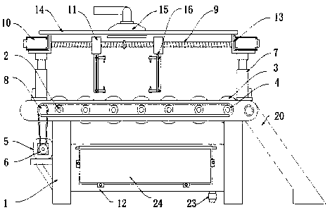
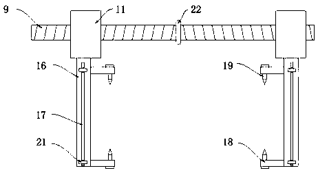
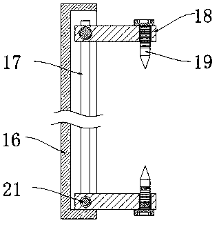
[0024] refer to Figure 1-4 , a fast demoulding device for wear-resistant castings, comprising a demoulding machine 1, a rectangular through hole is opened on the upper surface of the platen of the demoulding machine 1, the inner wall of the rectangular through hole is rotatably connected with a rotating shaft 2, and the surface of the rotating shaft 2 is fixed The rotating wheel 3 is sleeved, and the number of rotating shafts 2 is multiple, and the gap between the plurality of rotating wheels 3 fixedly sleeved on the surface of the rotating shaft 2 is 2-10 cm, and the rotating shaft 2 extends to the front of the demoulding machine 1. One end is fixedly connected with a sprocket 4, the left side of the support leg of the demoulding machine 1 is installed with a driving motor 5, the output shaft of the driving motor 5 is connected with a transmission wheel 6, and the front of the demoulding machine 1 is rotatably connected with an engaging wheel 8 , the connecting wheel 8 is co...

Embodiment 2

[0028] refer to figure 1 The difference from Example 1 is that the lower surface of the demoulding machine 1 is provided with a collection frame 12 for collecting foundry sand, the right end of the demoulding machine 1 is provided with a rotating connecting plate 20, and the lower surface of the cross bar 14 is installed with a High-pressure nozzle 15, the water inlet pipe of high-pressure nozzle 15 is connected with the output end of water pump, the lower surface of collection frame 12 is provided with drainage pipe 23, and the front of collection frame 12 is provided with rotary sealing door 24.

[0029] In this embodiment, by setting up the high-pressure nozzle 15, after the sand mold template is separated, the high-pressure water delivered by the high-pressure nozzle 15 is used to wash the foundry sand with high intensity, and the washed sand flows into the collection frame 12, so that the casting The foundry sand on the surface is cleaned, which avoids manual cleaning and...


PUM


Abstract

The invention discloses a rapid demolding device for a wear-resistant casting. The rapid demolding device comprises a demolding machine table, wherein a rectangular through hole is formed in the uppersurface of a table plate of the demolding machine table, a rotating shaft is rotationally connected to the inner wall of the rectangular through hole, a rotating wheel fixedly sleeves the surface ofthe rotating shaft, the end, extending to the front face of the demolding machine table, of the rotating shaft is fixedly connected with a chain wheel, and a driving motor is mounted on the left sideof a supporting leg of the demolding machine table. According to the rapid demolding device for the wear-resistant casting, the vertical distance between two threaded clamping nails is convenient to adjust by arranging height adjusting bolts, so that the rapid demolding device is suitable for sand mold wooden templates of different sizes, and a demolding motor is arranged to drive a driving lead screw to rotate, so that two lead screw nut blocks move oppositely or relatively for generating relative pulling force, and shells of the sand mold wooden templates are separated; and meanwhile, the rotating shaft is further arranged to drive a transmission wheel to rotate, so that the sand mold templates are convenient to convey and concentrate, and manpower is saved.

Description

technical field [0001] The invention relates to the technical field of wear-resistant castings, in particular to a quick demoulding device for wear-resistant castings. Background technique [0002] Steel, iron and most non-ferrous alloy castings can be obtained by sand casting. Because the molding materials used in sand casting are cheap and easy to obtain, the casting mold is easy to manufacture, and it can adapt to the single-piece production, batch production and mass production of castings. It has been the basic process in casting production for a long time. [0003] The mold used in sand casting is generally composed of an outer sand mold and a core. The whole production process is divided into: modeling-core-making-drying-box-closing-casting-shaking-cleaning-surface treatment. After pouring and cooling, the molten iron and molten steel are cooled and formed inside, and the internal casting needs to be taken out after forming. [0004] Most of the existing mechanical...

Claims


Application Information

Patent Timeline
Patent Type & Authority Applications(China)
IPC IPC(8): B22D29/04B08B3/02
CPCB08B3/02B22D29/04
Inventor 费昭鹤
Owner 安徽省安工机械制造有限公司
Why Eureka
Eureka Blog
Learn More