Eureka AIR delivers breakthrough ideas for toughest innovation challenges, trusted by R&D personnel around the world.

Device and method for measuring spool displacement based on laser displacement sensor

A technology of laser displacement and valve core displacement, applied in measurement devices, optical devices, instruments, etc., can solve the problems of valve core resistance, high cost, valve performance impact, etc., to improve measurement accuracy, simple structure, and strong applicability. Effect

Active Publication Date: 2019-05-14
TIANJIN TRINOVA AUTOMOTIVE TECH CO LTD
View PDF11 Cites 0 Cited by
  • Summary
  • Abstract
  • Description
  • Claims
  • Application Information

AI Technical Summary

Problems solved by technology

For example, the method disclosed in the patent No. CN1587893A measures the displacement of the valve core through the method of high-voltage eddy current displacement sensor, which needs to destroy the structure of the valve body itself, which will have a certain impact on the performance of the valve, and the cost is relatively expensive.
The high-pressure pilot-operated pneumatic solenoid valve spool displacement measuring device and method disclosed in Patent No. CN103438807A mainly uses a laser displacement sensor to measure the spool displacement transmission device to obtain the spool displacement, but this method causes relatively large resistance to the spool. It also has a certain impact on the performance of the valve and cannot achieve high-precision measurement
The automatic detection device and method for solenoid valve core displacement disclosed in Patent No. CN102692200A uses a probe to measure the displacement of the valve core, but considering that the valve has no sealing structure, it is impossible to measure the displacement of the valve core in other types of valves
[0004] Therefore, for the high-speed switching valve in the hydraulic control unit, because the valve core is sealed in the valve body, it is difficult to measure the displacement of the valve core. At present, there is no relatively mature equipment and method for measurement.

Method used


Image

  • Device and method for measuring spool displacement based on laser displacement sensor
  • Device and method for measuring spool displacement based on laser displacement sensor
  • Device and method for measuring spool displacement based on laser displacement sensor

Examples


Embodiment Construction

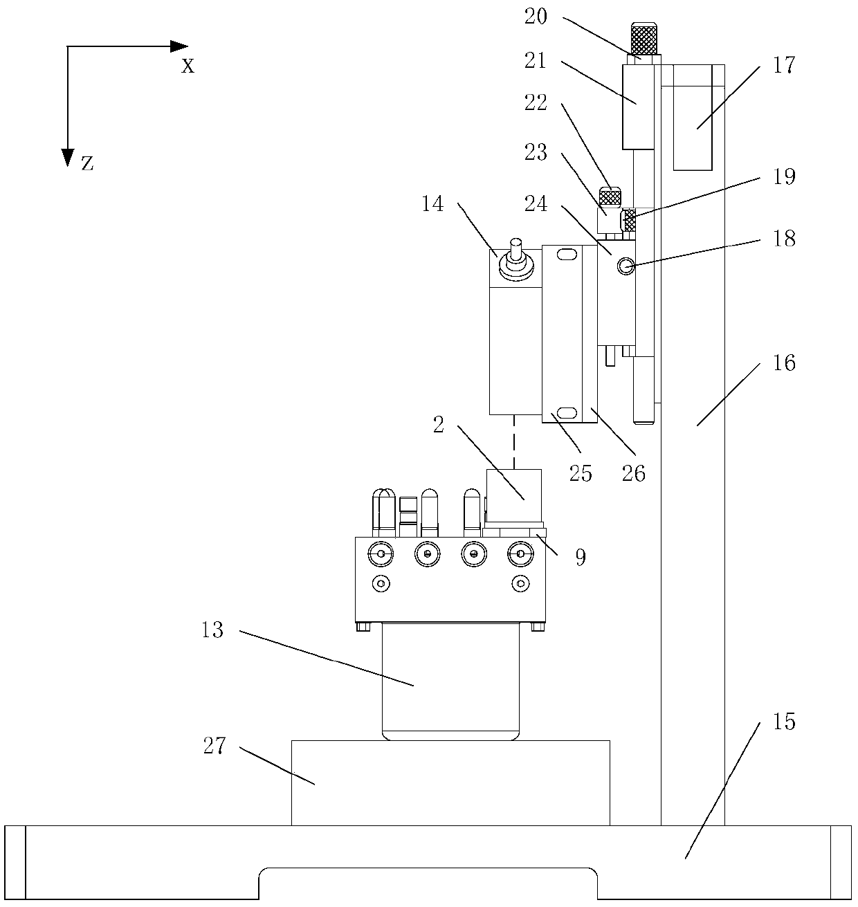
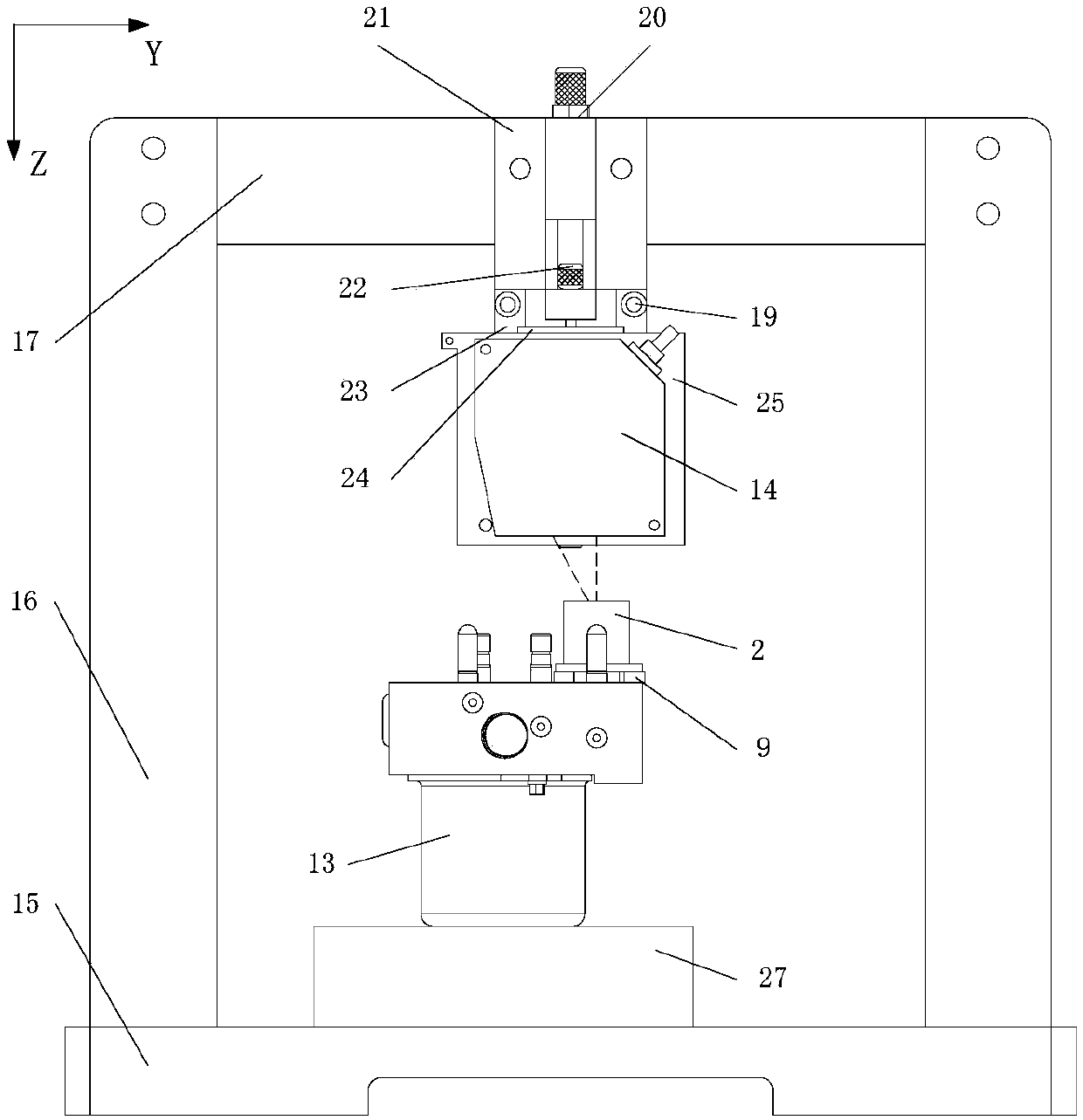
[0036] Attached below Figure 1-13 The present invention is described in detail.

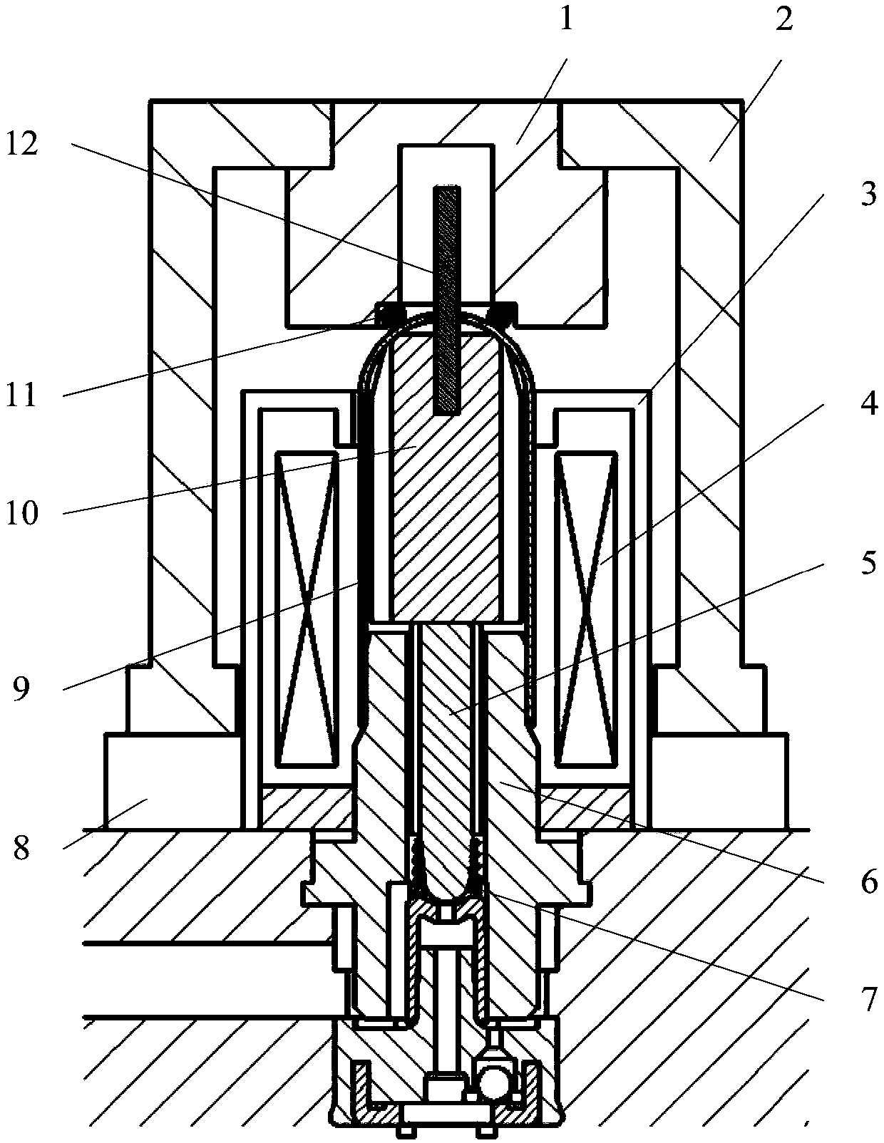
[0037] Such as image 3 and Figure 4 As shown, the detection object of the present invention is the high-speed on-off valve in the hydraulic control unit. To illustrate the structure of the on-off valve, one should first understand the HCU13, the spool displacement transmission device and the valve sealing device.

[0038] Wherein: HCU13 is the important part of automobile, and it comprises valve body, booster valve, decompression valve etc., introduces the present invention in detail with booster valve as example below, booster valve mainly comprises shell 3, coil 4, spool 5, Valve seat 6, spring 7, magnetic isolation tube 9 and moving iron 10; the external environment supplies power to the coil 4, thereby generating a magnetic field, and the moving iron 10 generates axial movement under the action of electromagnetic force, etc., because the spring 7 has a pre-tightening force , so that the...


PUM


Abstract

The invention discloses a valve core displacement measurement device based on a laser displacement sensor. The valve core displacement measurement device comprises a valve core displacement test bench and a signal acquisition and processing device. The valve core displacement test bench comprises a fixed support and an adjustable support. The signal acquisition and processing device comprises the laser displacement sensor (14), a signal amplifier and a computer. The laser displacement sensor (14) is connected with the signal amplifier and the computer so as to establish a signal transmission channel. The signal amplifier transmits the signals acquired by the laser displacement sensor (14) to the computer through signal amplification. The signals are processed in the computer so that the required digital signals are obtained, and the valve core displacement is determined by the digital signals. The valve core displacement can be directly measured so that the measurement accuracy can be enhanced.

Description

technical field [0001] The invention belongs to the displacement measurement technology of a solenoid valve core, in particular to a device and a method for measuring the displacement of a valve core in a hydraulic control unit of an active safety system of an automobile. Background technique [0002] As an important part of the vehicle dynamics control system, the hydraulic control unit has higher and higher application requirements. In the transient high-frequency brake pressure control process required in active safety systems, accurate linear control of the brake pressure on the hydraulic control unit can greatly improve the performance of the brake system and reduce noise and braking in the hydraulic control unit. Disk vibration. The displacement value of the booster valve is an important feedback quantity in the linear control system. Therefore, the solenoid valve spool displacement measuring device that can accurately obtain the displacement of the booster valve spoo...

Claims


Application Information

Patent Timeline
Patent Type & Authority Patents(China)
IPC IPC(8): G01B11/02
CPCG01B11/026
Inventor 李亮赵洵俞伟高祥
Owner TIANJIN TRINOVA AUTOMOTIVE TECH CO LTD
Why Eureka
Eureka Blog
Learn More