Ventilation air bag and preparation method and mold thereof

A technology of airbags and molds, which is applied to other household appliances, household appliances, household components, etc., can solve the problems of high production cost, many airbag components, complex structure, etc., achieve good airtightness, simplify the production process, and simplify the structure of the airbag Effect

Pending Publication Date: 2020-07-28
袁大彩
View PDF0 Cites 6 Cited by
  • Summary
  • Abstract
  • Description
  • Claims
  • Application Information

AI Technical Summary

Problems solved by technology

There are many airbag components, manual assembly is required, the structure is complex, and the production cost is high

Method used


Image

  • Ventilation air bag and preparation method and mold thereof
  • Ventilation air bag and preparation method and mold thereof
  • Ventilation air bag and preparation method and mold thereof

Examples


Embodiment 1

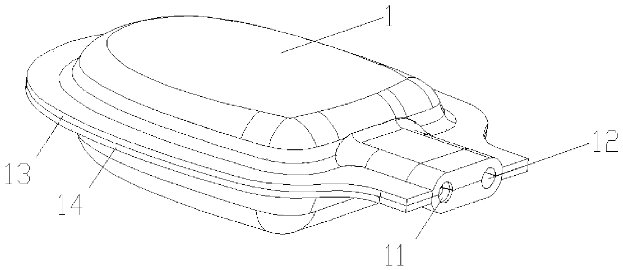
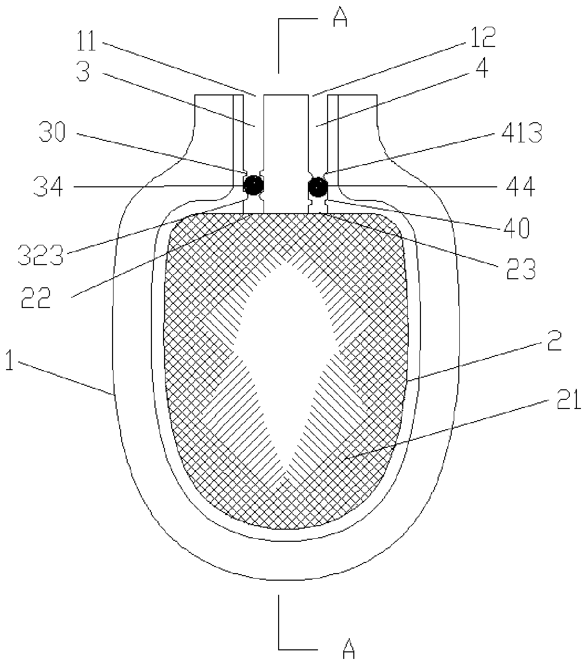
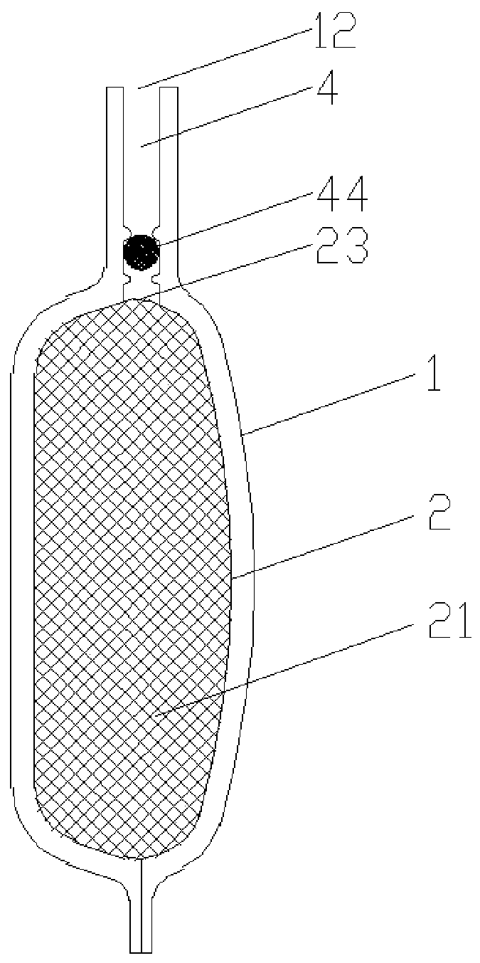
[0037] see Figure 1-9 As shown, the present invention relates to a ventilation airbag, including an airbag body 1, the airbag body 1 is made of rubber, the airbag body 1 includes an airbag upper sheet 13 and an airbag lower sheet 14, and the airbag body 1 is provided with a Air cavity 2, the air-containing inner cavity 2 is provided with breathable support fillers 21, such as sponges, leaves, etc., the front end of the airbag body 1 is provided with an air inlet 11 and an air outlet 12, and the air-containing inner cavity 2 It has an inlet 22 and an outlet 23, and a one-way air intake channel 3 communicating with the air-containing inner cavity 2 is provided between the air inlet 11 and the inlet 22 of the air-containing inner cavity 2, and between the air outlet 12 and the outlet 23 of the air-containing inner cavity 2 There is a one-way outlet flow channel 4 communicating with the air-containing inner cavity 2. The airbag body 1, the one-way inlet flow channel 3 and the one...

Embodiment 2

[0056] The difference between Embodiment 2 and Embodiment 1 is that the structures of the inlet runner 3 and the outlet runner are different, and the structure of the inlet runner mold core and the outlet runner mold core are different.

[0057] In the second embodiment, the air intake channel 3 includes a first air intake section 31, a second air intake section 32 and a first interface 33 communicating with the first air intake section 31 and the second air intake section 32. The air inlet section 32 is provided with a first ball 34 that opens or closes the first interface 33, and the outlet flow channel 4 includes a first air outlet section 41, a second air outlet section 42 and a first air outlet section 41 and a second air outlet section 42 connected to each other. The second interface 43 of the section 42, the first air outlet section 41 is provided with a second ball 44 for opening or closing the second interface 43.

[0058]Preferably, the first air intake section 31 is...


PUM


Abstract

The invention relates to a ventilation air bag and a preparation method and mold thereof. The ventilation air bag comprises an air bag body, wherein an air containing inner cavity is formed in the airbag body, a one-way air inlet flow channel and a one-way air outlet flow channel which communicate with the air containing inner cavity are formed in the front end of the air bag body, and balls arearranged in the air inlet flow channel and the air outlet flow channel correspondingly; the air inlet flow channel and the air outlet flow channel comprise pipelines and closing rings which are arranged in the pipelines and are smaller than the inner diameters of the pipelines, a plurality of limiting points protrude on the inner walls of the flow channels, and the closing rings are matched with the balls to open or close the air circulation of the flow channels; and the limiting points of the air inlet flow channel limit the balls to fall into the air containing inner cavity and keep the flowchannels ventilated, the closing rings of the air outlet flow channel are matched with the balls to open or close the air circulation of the air outlet flow channel, and the limiting points of the air outlet flow channel limit the balls to run out of the air bag and keep the flow channels ventilated. The ventilation air bag is simple in structure, the air inlet flow channel and the air outlet flow channel are integrally formed in the air bag body, the balls move between the closing rings and the limiting points correspondingly to achieve the effects of one-way air inlet and one-way air outlet, and the overall structure is simplified.

Description

technical field [0001] The invention relates to the technical field of footwear, in particular to a ventilation airbag, a preparation method thereof and a mold. Background technique [0002] When a person walks, the feet bear the weight of the whole body and transmit this weight to the ground, and the opposite ground will also generate a reaction force to the feet, so we will feel sore feet after walking for a while. In order to solve this problem, The shoe factory will add some ventilation airbags on the soles, and use the airbags to increase the resilience to achieve shock absorption, so as to improve the wearer's walking comfort. At present, the airbags are made of TPU hollow capsules, which need to be cut and glued manually. The knot forms an air bag shape, and the bag body cuts out a joint communicating with the air cavity of the bag body; an air guide tube is inserted at the joint, and a one-way valve core is inserted at the end of the air guide tube. The airbag has m...

Claims


Application Information

Patent Timeline
Patent Type & Authority Applications(China)
IPC IPC(8): B29C33/00B29L22/02B29L31/50
CPCB29C33/00B29L2022/027B29L2031/504
Inventor 袁大彩
Owner 袁大彩
Why Eureka
Try Eureka