Sheath blowing machine

A sheathing machine and sheathing technology, which are applied to household components, household appliances, other household appliances, etc., can solve problems such as difficulty in passing through sheaths, limiting cable processing efficiency, and limiting processing costs.

Pending Publication Date: 2020-07-28
余姚市镒万金属软管有限公司
View PDF0 Cites 3 Cited by
  • Summary
  • Abstract
  • Description
  • Claims
  • Application Information

AI Technical Summary

Problems solved by technology

[0003] The glass lifter is driven by the output shaft of the motor to rotate the wire wheel body to realize the lifting of the glass. In order to avoid the noise caused by the collision between the cable and the inner wall of the car door when the glass is lifted, a shock-absorbing sheath is generally installed on the cable. The sheath surrounds the cable and is soft in texture. After the cable is processed, the combined installation of the cable and the sheath is usually done manually. Since the holes at both ends of the sheath are similar to the caliber of the cable, it is difficult for the cable to pass through. The sheath greatly limits the processing efficiency of the cable, and the manpower input limits the processing cost

Method used


Image

  • Sheath blowing machine
  • Sheath blowing machine
  • Sheath blowing machine

Examples


Embodiment 1

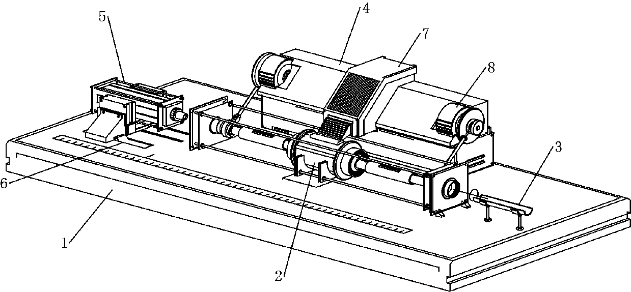
[0038] This embodiment comprises that above-mentioned main cabinet 4 contains all mechanical control equipments, and this sheath blowing machine is controlled according to the PLC system setting program, after the power supply box 35 is connected to the on-site power supply by the operator during production, start the machine through the control panel 33 and start the machine. operate.

[0039] The input end of the connection panel 34 is electrically connected to the connection cable 12, the drive motor 19 and the output end of the displacement motor 41;

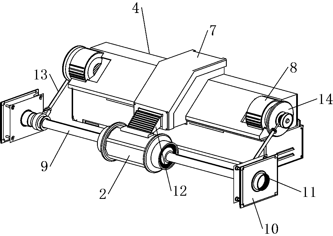
[0040] A sheath sleeve 9 is plugged into the left and right ends of the expansion cylinder seat 2, the sheath sleeve 9 communicates with the inner tube 30, a sleeve 15 is sleeved in the middle of the sheath sleeve 9, and the sheath sleeve 9 is in addition One end is sleeved with a sealing plug 16, and the outer side of the sealing plug 16 is adjacent to a handle seat 10, and the middle opening of the handle seat 10 is provid...

Embodiment 2

[0044] On the basis of the above-mentioned embodiment, the production personnel inserts the sheath into the plug opening 11 along the surface of the handle seat 10 at the left end, and inserts it into the sheath tube 9 at the left end. As the sheath goes deeper, the other end of the sheath will pass through the expansion cylinder seat 2 Insert in the right end sheath casing 9;

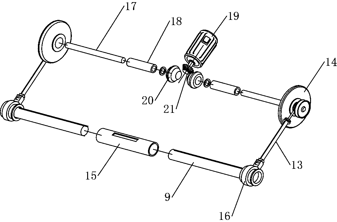
[0045] At this time, the main engine 7 controls the drive motor 19 to brake, and the drive motor 19 rotates forward and drives the right-hand transmission shaft 17 to rotate forward through the crankshaft bevel gear 21 and the bevel gear 20, and the left-hand transmission shaft 17 is reversed. At this time, the right-hand transmission shaft 17 The shaft joint 18 and the connecting gear 24 will be used to drive the right-end shaft seat plate 14 to be driven, and the shaft core 23 will be rotated forward along the bearing 25 synchronously. Roll up and pull the other end located in the sealing plug 16. Af...

Embodiment 3

[0048] After the above-mentioned embodiment, the main engine 7 controls the displacement motor 41 to brake, and the displacement motor 41 drives the threaded shaft 39 to be driven, and the ball screw 40 threadedly connected with the threaded shaft 39 will carry out lateral translation along with the threaded shaft 39 screwing in direction, And synchronously drive the rail seat 36 to move along the track groove 6. After the rail seat 36 moves to the right end limit position along the track groove 6, the right end of the cylinder 5 will insert the insertion head 38 into the left end inlet and outlet plug port 11, and pass through the cylinder 5 along the inlet and outlet plug port. 11. The sheath casing 9 is inflated into the sheath.

[0049] An inner tube 30 is provided through the middle of the inner side of the expansion cylinder seat 2, and a strain patch 31 is distributed circularly on the outer middle of the inner tube 30. The cable 12 is electrically connected to the inpu...


PUM


Abstract

The invention discloses a sheath blowing machine, and belongs to the technical field of vehicle body part machining. The machine comprises a machining platform, an expansion cylinder seat, a main cabinet and an air cylinder; the expansion cylinder seat, the main cabinet and the air cylinder are all arranged on the upper surface of the machining platform, the air cylinder and the expansion cylinderseat are distributed from left to right and are axially aligned, and the main cabinet is adjacently arranged at the rear end of the expansion cylinder seat; an inner pipe is arranged in the middle ofthe inner side of the expansion cylinder seat in a penetrating mode, a strain gauge is annularly arranged in the middle of the outer side of the inner pipe, and the four corners of the surface of thestrain gauge are connected with probes in series; and connecting cables are inserted into the upper end of the expansion cylinder seat, and the input ends of the connecting cables are electrically connected with the output ends of the probes. According to the machine, sheaths are successively subjected to sealing, air inflating, and inhaul cable inserting through a machining mechanism controlledby a host system, combined mounting on the inhaul cable sheaths is completed by the machine through the automatically-controlled machining mechanism, and compared with a traditional manual productionmode, the machine has the beneficial effects that the machining efficiency is improved, and the machined product quality of the inhaul cable sheaths is guaranteed through the machine.

Description

technical field [0001] The invention relates to the technical field of car body parts processing, in particular to a sheath blowing machine. Background technique [0002] The glass lifter is the lifting device for the door and window glass of the car. It is mainly divided into two categories: the electric glass lifter and the manual glass lifter. Nowadays, the lifting of the door and window glass of many cars is generally switched to the push-button electric lifting method, and the electric glass lifter is used. Among them, the glass lifter cable is an important part of the glass lifter; [0003] The glass lifter is driven by the output shaft of the motor to rotate the wire wheel body to realize the lifting of the glass. In order to avoid the noise caused by the collision between the cable and the inner wall of the car door when the glass is lifted, a shock-absorbing sheath is generally installed on the cable. The sheath surrounds the cable and is soft in texture. In the po...

Claims


Application Information

Patent Timeline
Patent Type & Authority Applications(China)
IPC IPC(8): B29C63/18B29L31/30
CPCB29C63/0004B29C63/18B29L2031/30
Inventor 沈云炜
Owner 余姚市镒万金属软管有限公司
Why Eureka
Try Eureka