Screen printing machine

A technology for a screen printing machine and a screen printing device, which is applied to screen printing machines, printing machines, rotary printing machines, etc., can solve the problems of affecting printing accuracy, high operating frequency, and high overall cost, so as to improve printing accuracy, The effect of high operating frequency and improved accuracy

Pending Publication Date: 2020-07-28
LIANCHENG KEKESI TECH CO LTD
View PDF0 Cites 2 Cited by
  • Summary
  • Abstract
  • Description
  • Claims
  • Application Information

AI Technical Summary

Problems solved by technology

[0002] The rotating table and roll paper base of the existing equipment are designed separately, the overall weight is relatively large, and the distribution is far from the center of the rotating table, the inertia is large when rotating, which affects the overall printing accuracy; the roll paper group is transmitted by a synchronous belt and a synchronous wheel, Not only the overall cost is high, but also due to the high frequency of operation, the wear is relatively large, and because of its compact structure, maintenance is relatively difficult

Method used


Image

  • Screen printing machine
  • Screen printing machine
  • Screen printing machine

Examples


Embodiment Construction

[0030] In order to make the above objects, features and advantages of the present invention more comprehensible, specific implementations of the present invention will be described in detail below in conjunction with the accompanying drawings. In the following description, numerous specific details are set forth in order to provide a thorough understanding of the present invention. However, the present invention can be implemented in many other ways different from those described here, and those skilled in the art can make similar improvements without departing from the connotation of the present invention, so the present invention is not limited by the specific embodiments disclosed below.

[0031] Unless otherwise defined, all technical and scientific terms used herein have the same meaning as commonly understood by one of ordinary skill in the technical field of the invention. The terms used herein in the description of the present invention are for the purpose of describin...


PUM


Abstract

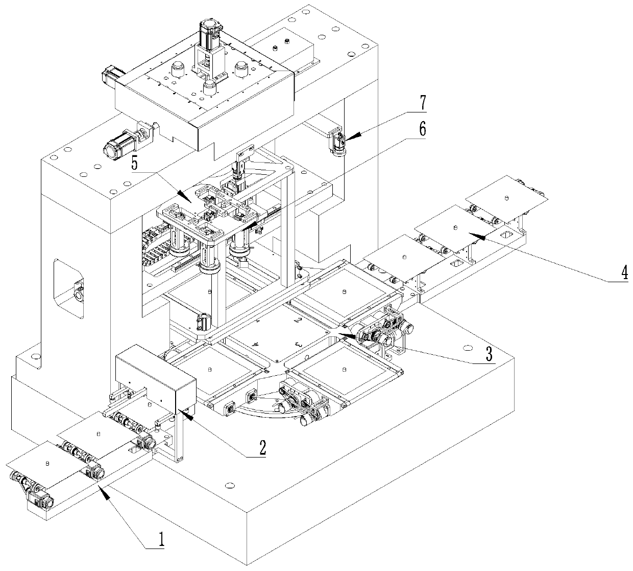
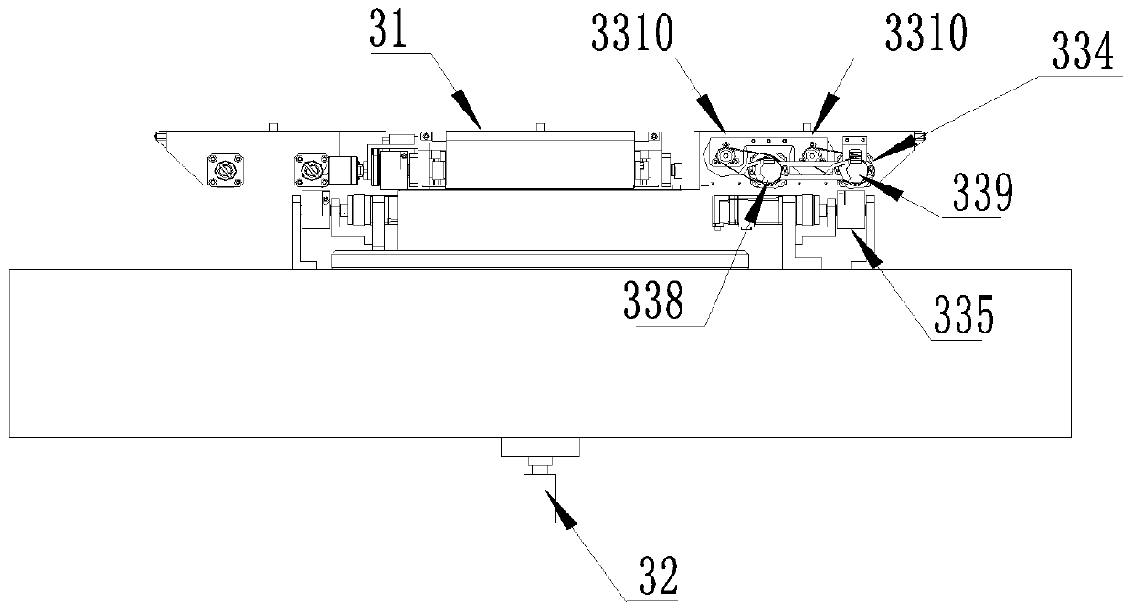
The invention discloses a screen printing machine. The screen printing machine comprises a bottom plate. The bottom plate is sequentially provided with an inlet slice conveying mechanism, a rotating platform group and an outlet slice conveying mechanism. The rotating platform group comprises a rotating frame and a rotation drive mechanism driving the rotating frame to do rotating movement. A plurality of silicon wafer placement conveying platforms are arranged on the rotating platform in the circumferential direction. An inlet slice detection positioning mechanism, a screen printing device andan outlet slice detection mechanism are arranged on the circumferential side of the rotating frame, the silicon wafer placement conveying platforms sequentially move to the positions below the detection positioning mechanism, the screen printing device and the outlet slice detection mechanism in the rotating process. The rotating platform assembly design is simplified, the rotating platform and the silicon wafer placement conveying platforms are integrally designed, the assembly installation space is reduced, the total weight is reduced, the assembly weight is drawn close to the center of therotating platform so that the rotation inertia can be reduced, the printing precision is improved, the silicon wafer placement conveying platforms carry out conveying in a non-contact manner, the conveying power is stable, and the precision is good.

Description

technical field [0001] The invention relates to the field of screen printing, in particular to a screen printing machine. Background technique [0002] The rotating table and roll paper base of the existing equipment are designed separately, the overall weight is relatively large, and the distribution is far from the center of the rotating table, the inertia is large when rotating, which affects the overall printing accuracy; the roll paper group is transmitted by a synchronous belt and a synchronous wheel, Not only the overall cost is high, but also due to the high frequency of operation, the wear and tear is relatively large, and because of its compact structure, maintenance is relatively difficult. Contents of the invention [0003] The technical problem solved by the invention is to provide a screen printing machine with compact structure and high printing progress. [0004] The technical solution adopted by the present invention to solve the technical problem is: a s...

Claims


Application Information

Patent Timeline
Patent Type & Authority Applications(China)
IPC IPC(8): B41F15/08B41F15/16B41F15/34B41F15/42B41F15/44B41F33/00
CPCB41F15/08B41F15/16B41F15/34B41F15/42B41F15/44B41F33/0036
Inventor 葛景李明亮
Owner LIANCHENG KEKESI TECH CO LTD
Why Eureka
Try Eureka