Prestressed concrete beam hogging moment area bridge structure and construction method thereof

A technology of negative bending moment area and bridge structure, which is applied in the direction of bridges, bridge parts, bridge materials, etc., can solve problems such as difficulty in threading wires, corrosion of steel strands, long construction period, etc., and achieves simple and fast construction methods and reasonable and reliable stress , the effect of good economic benefits

Active Publication Date: 2020-07-28
ZHEJIANG PROVINCIAL INST OF COMM PLANNING DESIGN & RES CO LTD
View PDF7 Cites 7 Cited by
  • Summary
  • Abstract
  • Description
  • Claims
  • Application Information

AI Technical Summary

Problems solved by technology

[0002] In recent years, the application of prestressed concrete in bridges has developed rapidly, and prestressing is often required in the negative moment area on the top of the pier. The traditional cast-in-place bridge deck applies prestressing methods by stretching the prestressed beams in the reserved panel tunnel. Each Both ends of the root prestressed beam need to be equipped with anchors. At the same time, additional processes such as retaining holes, piercing bars, grouting, and anchor sealing are added during the construction. The construction process is complicated and the construction period is long, which hinders the development of urban public transportation.
At the same time, the traditional prestressing post-tensioning method, anchorage corrosion, sliding anchor, steel strand corrosion, fracture; tunnel blockage, tunnel offset, etc. lead to problems such as wire threading difficulties, resulting in poor economic efficiency of the traditional prestressing method, which does not meet the national advocacy The concept of rapid construction and assembly

Method used


Image

  • Prestressed concrete beam hogging moment area bridge structure and construction method thereof
  • Prestressed concrete beam hogging moment area bridge structure and construction method thereof
  • Prestressed concrete beam hogging moment area bridge structure and construction method thereof

Examples


Embodiment

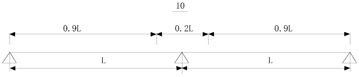
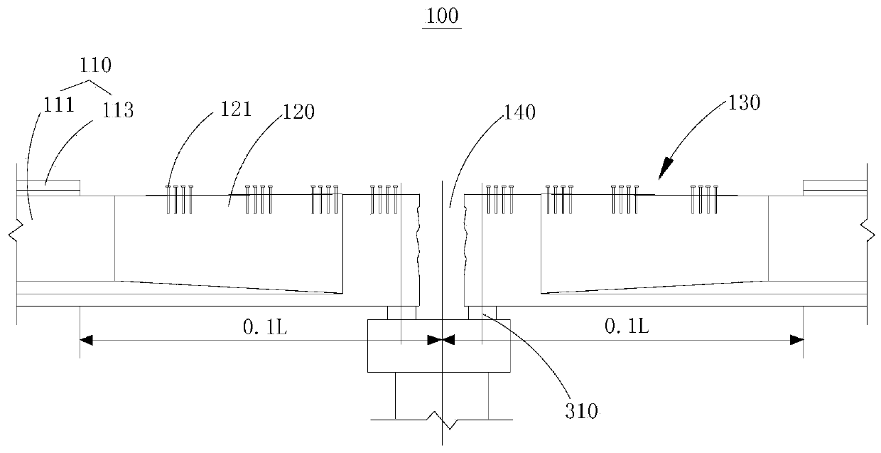
[0053] see Figure 1 to Figure 9 , the present embodiment provides a prestressed concrete beam bridge structure in the negative moment zone (hereinafter referred to as the bridge structure 10 ), which mainly includes a prefabricated T-beam 100 and a prefabricated bridge deck 200 .

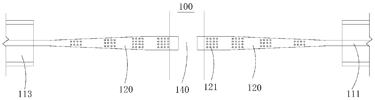
[0054] Among them, see figure 2 as well as image 3 , the prefabricated T-beam 100 includes a T-beam 110 installed in the positive moment region of the bridge structure 10 and a second beam rib 120 integrally formed with the T-beam 110 and installed in the negative moment region of the bridge structure 10, wherein the T-beam 110 And the second beam ribs 120 are arranged along the extending direction of the bridge structure. Wherein, the negative bending moment of the prefabricated T-beam 100 is within a range of 0.1L from the beam end of the second beam rib 120 .

[0055] It should be noted that the T-beam 110 is actually composed of the integrally formed first rib 111 and the wing plate 113 , ...


PUM


Abstract

The invention discloses a prestressed concrete beam hogging moment area bridge structure and a construction method thereof, and relates to the technical field of bridge engineering. The construction method of the prestressed concrete beam hogging moment area bridge structure comprises the steps that obtaining prefabricated T-shaped beams and a prefabricated bridge deck slab; hoisting the two prefabricated T-shaped beams to enable the two prefabricated T-shaped beams to be in butt joint, and forming a groove which is positioned in a hogging moment area and is used for mounting a prefabricated bridge deck slab between wing plates of the two adjacent T-shaped beams; after two adjacent beam ribs are connected, hoisting the prefabricated bridge deck slab in the groove, after the prefabricated bridge deck slab and wing plate at one side are connected on one side, applying a prestress to the prefabricated bridge deck slab at the other side, and connecting the prefabricated bridge deck slab atthe side with the corresponding wing plate and beam rib to form a whole for common loading. The construction method is simple, convenient and rapid, the obtained bridge structure in the hogging moment area of the prestressed concrete beam is reliable in stress, and the construction method has high use value and good economic benefits in new bridge construction and old bridge transformation.

Description

technical field [0001] The present application relates to the technical field of bridge engineering, in particular to a prestressed concrete beam negative moment area bridge structure and a construction method thereof. Background technique [0002] In recent years, the application of prestressed concrete in bridges has developed rapidly, and prestressing is often required in the negative moment area on the top of the pier. The traditional cast-in-place bridge deck applies prestressing methods by stretching the prestressed beams in the reserved panel tunnel. Each Both ends of the root prestressed beam need to be equipped with anchors. At the same time, additional processes such as hole retention, reinforcement penetration, grouting and anchor sealing are added during the construction. The construction process is complicated and the construction period is long, which hinders the development of urban public transportation. At the same time, the traditional prestressing post-ten...

Claims


Application Information

Patent Timeline
Patent Type & Authority Applications(China)
IPC IPC(8): E01D2/00E01D19/00E01D19/12E01D21/00E01D101/28
CPCE01D2/00E01D19/00E01D19/125E01D21/00E01D2101/28
Inventor 王昌将段亚军安风明马芹纲陈多董佳霖林光毅张贤卿
Owner ZHEJIANG PROVINCIAL INST OF COMM PLANNING DESIGN & RES CO LTD
Why Eureka
Try Eureka