Light steel keel composite wall body and implementation process

A light steel keel and composite wall technology, which is applied to walls, building components, thermal insulation and other directions, can solve the problems of complex manufacturing process of composite sandwich panels, no longer able to set external wall decoration layers, affecting the beauty of composite walls, etc. Superior fire resistance and moisture resistance, superior structural performance, and convenient construction

Pending Publication Date: 2020-07-28
江苏豪斯建设工程有限公司
View PDF0 Cites 0 Cited by
  • Summary
  • Abstract
  • Description
  • Claims
  • Application Information

AI Technical Summary

Problems solved by technology

[0003] Light steel keel composite wall is a new type of building material, which has the advantages of light weight, high strength, waterproof, shockproof, dustproof, sound insulation, sound absorption, constant temperature, etc., and also has the advantages of short construction period and simple construction. High-quality continuous hot-dip galvanized strips are used as raw materials and rolled by cold-bending process. The light room is used in ice coffins, terminal buildings, passenger stations, stations, theaters, shopping malls, factories, office buildings, old building renovations, Indoor decoration settings and other places; the cross-sectional shape of the keel currently used is "C"-shaped, and the composite sandwich panel is installed outside the light steel keel frame to make the composite wall have waterproof and fireproof properties, but the manufacturing of the composite sandwich panel The process is relatively complicated, and the production cost is high. At the same time, after the composite sandwich panel is installed, the exterior wall decoration layer cannot be installed, which affects the appearance of the composite wall.

Method used


Image

  • Light steel keel composite wall body and implementation process
  • Light steel keel composite wall body and implementation process
  • Light steel keel composite wall body and implementation process

Examples


Embodiment Construction

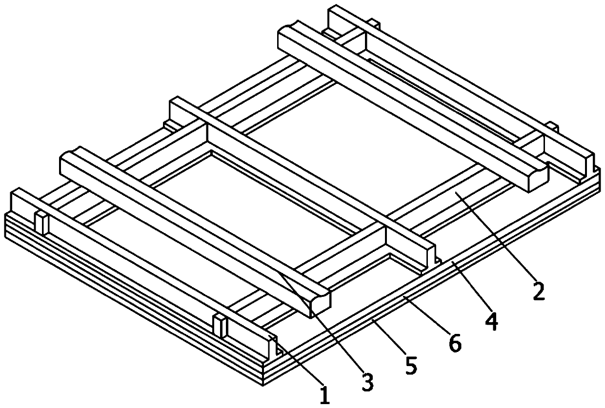
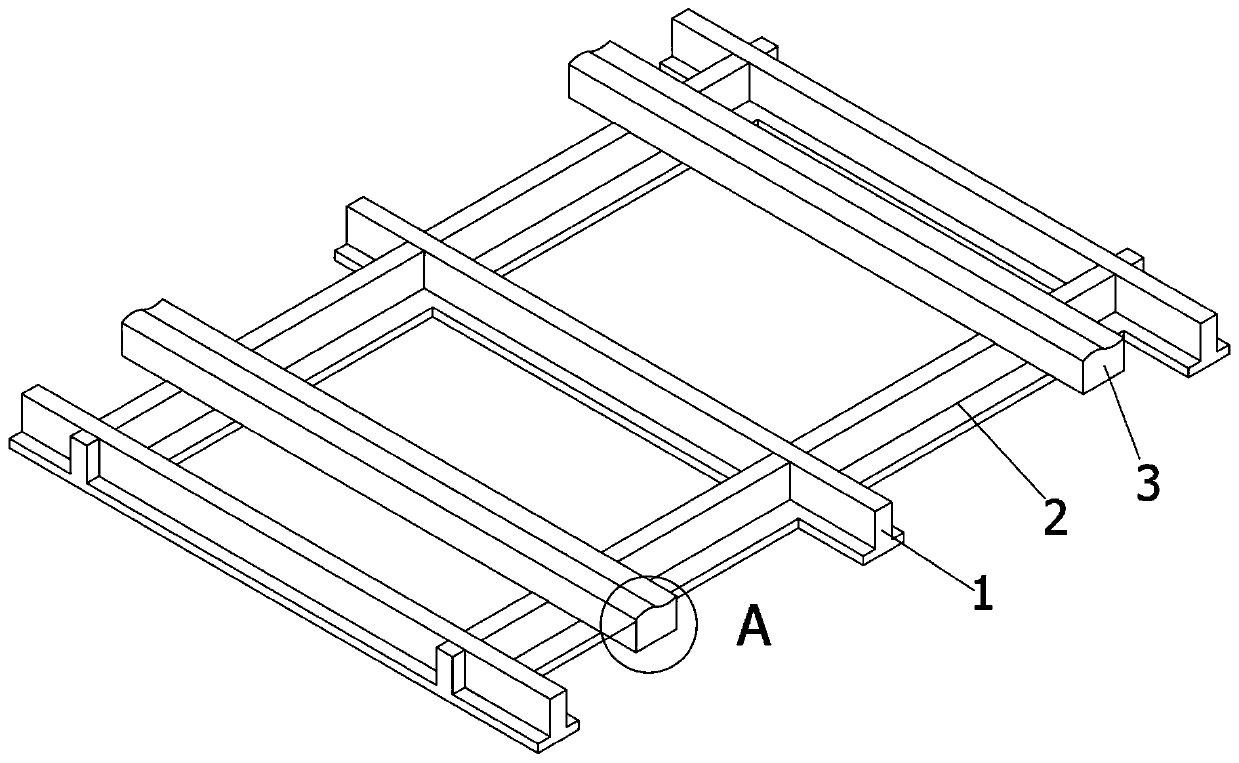
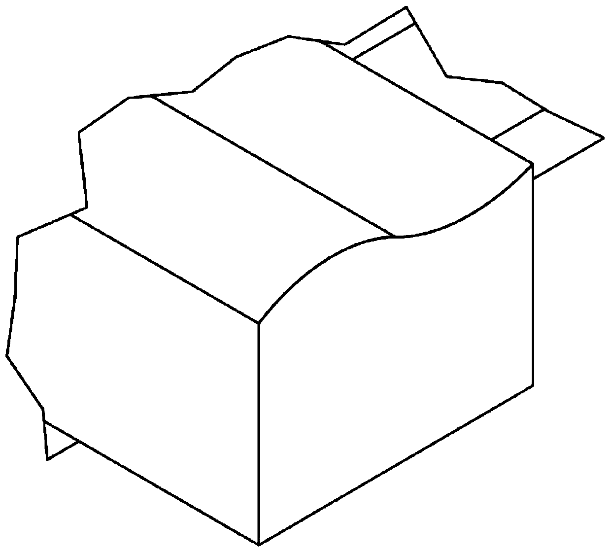
[0027] First of all, the original intention of the design of the present invention is to solve the problem that the cross-sectional shape of the keel currently used is a "C" shape, and by setting a composite sandwich panel outside the light steel keel frame, the composite wall has waterproof and fireproof properties, but The manufacturing process of the composite sandwich panel is relatively complicated, the production cost is high, and the exterior wall decoration layer cannot be installed, which affects the appearance of the composite wall; in order to change the shape of the keel to make it more suitable for the current wall market, the present invention Provided is a composite wall installed by using an S-shaped keel, thereby replacing the shortcomings of the existing composite wall structure, improving decorative performance, and facilitating installation and fixing of steel pipes.

[0028] In order to facilitate those skilled in the art to make this technical solution mor...


PUM


Abstract

The invention discloses a light steel keel composite wall body. The wall body comprises a light steel keel framework and a one-time forming composite wall body which is manufactured in a way that thelight steel keel framework is used as a formwork and concrete with the supplement of BY grouting materials are grouted. A calcium silicate plate is arranged on the light steel keel framework; a decorative layer is arranged on the outer side of the calcium silicate plate; the space between the calcium silicate plate and the decorative layer is filled with insulating mortar; the light steel keel framework comprises a light steel keel and a plurality of expansion bolts; the light steel keel comprises a corner keel, a connecting keel which is perpendicular to the corner keel, and an S-shaped keelwhich is arranged on a supporting element; the corner keel and the connecting keel are fixed to a beam slab of a building structure via the expansion bolts; the connecting keel are in a locking connection with the corner keel; and the S-shaped keel is connected with the connecting keel. The light steel keel composite wall body has the beneficial effects that construction is convenient and excellent fireproof performance and moisture resistance are realized.

Description

technical field [0001] The invention relates to the technical field of building materials, in particular to a light steel keel composite wall and its implementation process. Background technique [0002] The basic requirement for non-load-bearing infill walls is that their mass is small so as to reduce the load on the floor and slabs, and the thickness is thin to increase the usable area of ​​the building; sound insulation, water resistance, fire resistance, etc. are required according to the specific environment. [0003] Light steel keel composite wall is a new type of building material, which has the advantages of light weight, high strength, waterproof, shockproof, dustproof, sound insulation, sound absorption, constant temperature, etc., and also has the advantages of short construction period and simple construction. High-quality continuous hot-dip galvanized strips are used as raw materials and rolled by cold-bending process. The light room is used in ice coffins, ter...

Claims


Application Information

Patent Timeline
Patent Type & Authority Applications(China)
IPC IPC(8): E04B2/74E04B2/78E04B2/82E04B2/86E04B1/76
CPCE04B1/76E04B2/7407E04B2/7409E04B2/7457E04B2/78E04B2/86E04B2001/7691
Inventor 李凯李鑫李小军陈卫星陆宁杰
Owner 江苏豪斯建设工程有限公司
Why Eureka
Try Eureka