Breather valve for spring braking air chamber and spring braking air chamber

A spring brake air chamber, breathing valve technology, applied in the direction of brake actuator, pipeline arrangement, gear transmission mechanism, etc., can solve the problems of difficult maintenance, complex internal breathing structure, etc., to achieve long service life, parts and components. Less usage and simple maintenance

Pending Publication Date: 2020-07-28
ZHEJIANG VIE SCI & TECH
View PDF1 Cites 1 Cited by
  • Summary
  • Abstract
  • Description
  • Claims
  • Application Information

AI Technical Summary

Problems solved by technology

[0005] The present invention provides a breathing valve for a spring braking air chamber, aiming at the disadvantages of complex internal breathing structure and difficult follow-up maintenance in the prior art.

Method used


Image

  • Breather valve for spring braking air chamber and spring braking air chamber
  • Breather valve for spring braking air chamber and spring braking air chamber
  • Breather valve for spring braking air chamber and spring braking air chamber

Examples


Embodiment 1

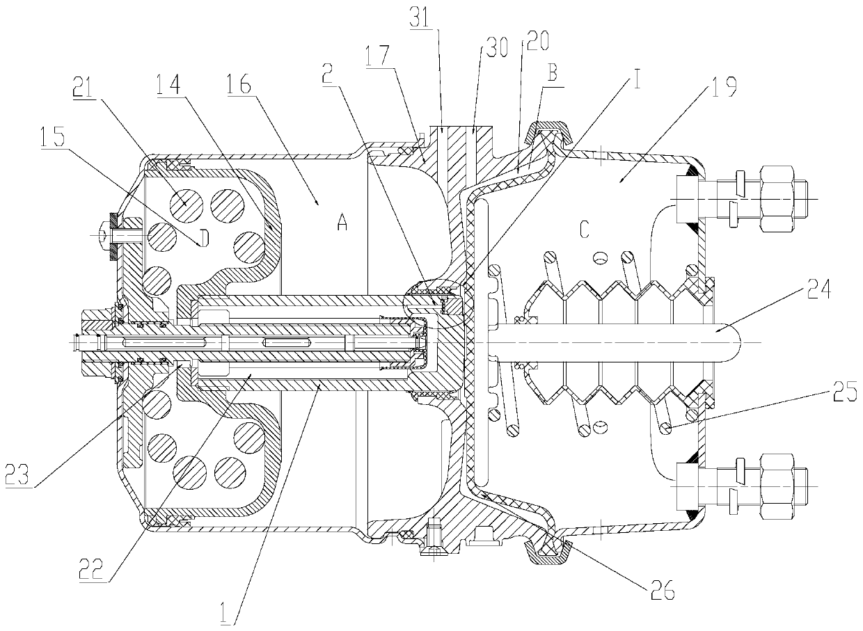
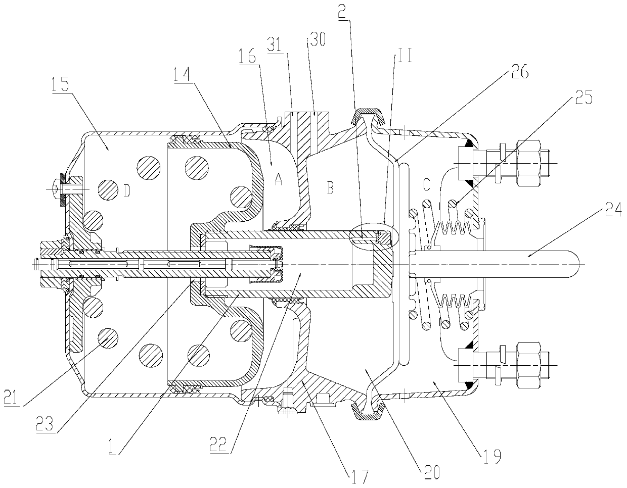
[0028] Such as Figure 1 to Figure 8 As shown, the breather valve used for the spring brake chamber, the breather valve structure is an internal breather structure. The breathing valve includes a piston rod 1, wherein the middle part of the piston rod 1 is a hollow structure, and a ventilation channel 2 is arranged in the piston rod 1, so the compressed air in the spring chamber D15 can enter the breathing channel through the hollow structure.

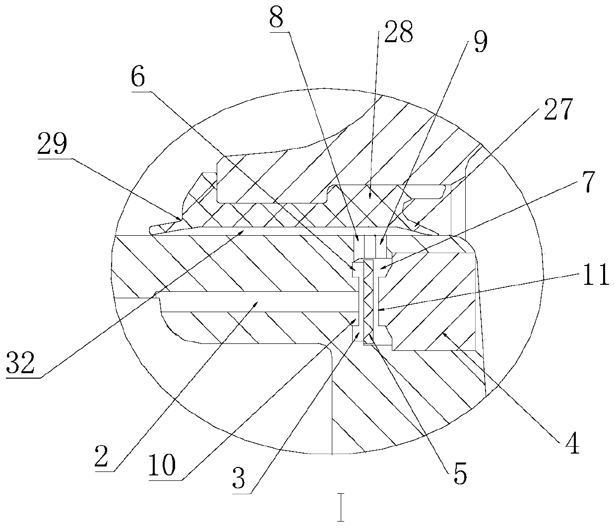
[0029] Wherein the breathing structure includes a breathing chamber 3 arranged in the piston rod 1 , specifically the breathing chamber 3 is arranged at the end of the piston rod 1 . One end of the breathing chamber 3 is provided with a plug 4, and the plug 4 is a detachable plug 4, so the processing method of the breathing chamber 3 is: a cavity is provided at one end of the piston rod 1, so that the cavity can be connected with the ventilation channel 2 Connected, and then place the valve plate 5 and install the plug 4.

[0030] It...

Embodiment 2

[0036] Such as Figure 1 to Figure 8As shown, this embodiment discloses a spring brake air chamber, and the spring brake air chamber includes the breathing valve described in Embodiment 1. The spring brake air chamber includes a parking chamber and a driving chamber, and a first piston 14 is arranged in the parking chamber, and the first piston 14 divides the parking chamber into a spring chamber D15 and a parking chamber A16, and also includes a valve body 17. The vehicle compartment and the driving compartment are located on both sides of the valve body 17. A diaphragm 26 is arranged in the driving compartment, and the diaphragm 26 divides the forming chamber into a spring chamber C19 and a driving chamber B20; Collision on the first piston 14, the first piston 14 is connected with the piston rod 1, the first piston 14 and the piston rod 1 move synchronously, and the middle part of the piston rod 1 is provided with a cavity 22, which is the hollow structure described in Embo...

Embodiment 3

[0044] The difference between this embodiment and Embodiment 1, Embodiment 2, and Embodiment 3 is that a first boss 12 is provided on the left side of the valve plate 5 , and a second boss 13 is provided on the right side.


PUM


Abstract

The invention relates to the field of spring braking air chambers, and discloses a breather valve for a spring braking air chamber. The breather valve comprises a piston rod, a ventilation channel isarranged in the piston rod, a breathing cavity is formed in the piston rod, a plug is arranged at one end of the breathing cavity, the ventilation channel communicates with the breathing cavity, a valve plate is arranged in the breathing cavity, the valve plate isolates the breathing cavity into a first breathing cavity and a second breathing cavity which not communicate with each other, the ventilation channel communicates with the first breathing cavity, and the ventilation channel does not communicate with the second breathing cavity. A first breathing hole and a second breathing hole are formed in the piston rod, the first breathing hole always communicates with the first breathing cavity, and the second breathing hole always communicates with the second breathing cavity. The breathingstructure has the advantages of simple structure, convenient installation, low follow-up maintenance cost and long service life.

Description

technical field [0001] The invention relates to the field of vehicle braking, in particular to a breather valve for a spring brake air chamber. Background technique [0002] The spring brake chamber is an integral part of the car brake system, which is usually installed on the drive axle of the car to provide the car with braking torque. In the actual working process, the spring brake chamber needs to be equipped with a breathing valve to realize the circulation of gas between different chambers; the current common design structure of the spring brake chamber is an external breathing tube spring brake The air chamber, because the front cavity, the rear cavity and the outside world communicate with each other, the external structure of the breathing tube is very easy to absorb moisture, sediment and other dirt during the work process, which will cause damage to the brake spring and sealing ring; in addition, in road conditions In a bad situation, the snorkel is easy to fall ...

Claims


Application Information

Patent Timeline
Patent Type & Authority Applications(China)
IPC IPC(8): F16D65/14B60T17/04F16D121/04F16D125/08F16D125/12
CPCB60T17/04F16D65/14F16D2121/04F16D2125/08F16D2125/12
Inventor 王语风吕芳王宸撼
Owner ZHEJIANG VIE SCI & TECH
Why Eureka
Try Eureka