Oil receiving method for reducer of pumping unit in oil field

A machine reducer and reducer technology, which is applied in the direction of mechanical equipment, gear lubrication/cooling, belt/chain/gear, etc., can solve the problems of complex manufacturing and installation, lower speed, and difficulty in effectively meeting the lubrication requirements of the reducer, so as to achieve saving cost, work efficiency improvement effect

Active Publication Date: 2021-10-22
苏海燕
View PDF7 Cites 0 Cited by
  • Summary
  • Abstract
  • Description
  • Claims
  • Application Information

AI Technical Summary

Problems solved by technology

[0003] The reducer is a key component of the pumping unit in the oil field. Its function is to reduce the speed and increase the torque. The reducer is one of the main wearing parts of the pumping unit. Improving the lubrication method can not only save resources, but also increase the load capacity of the reducer capacity and prolong the life of the pumping unit. In the prior art, the installation of lubrication devices is mostly used for oil lubrication, but the existing lubrication devices generally have the problems of complicated manufacturing and installation and difficulty in effectively meeting the lubrication requirements of the bearings of each shaft of the reducer.

Method used


Image

  • Oil receiving method for reducer of pumping unit in oil field
  • Oil receiving method for reducer of pumping unit in oil field
  • Oil receiving method for reducer of pumping unit in oil field

Examples


Embodiment Construction

[0029] The following will clearly and completely describe the technical solutions in the embodiments of the present invention with reference to the accompanying drawings in the embodiments of the present invention. Obviously, the described embodiments are only some, not all, embodiments of the present invention. Based on the embodiments of the present invention, all other embodiments obtained by persons of ordinary skill in the art without making creative efforts belong to the protection scope of the present invention.

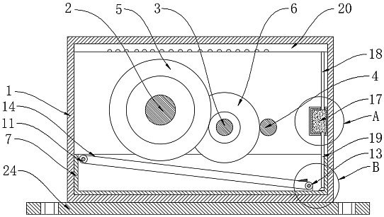
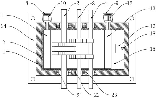
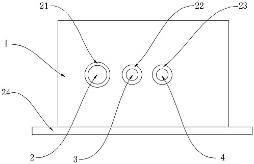
[0030] see Figure 1-5 , the present invention provides a technical solution: a method for receiving oil for an oil field pumping unit reducer, the oil receiving device includes a device box 1, the lower surface of the device box 1 is fixedly installed with a mounting plate 24, and the upper surface of the mounting plate 24 is opened There are four mounting holes for installing the mounting plate 24, and the four mounting holes are respectively located at the ...


PUM


Abstract

The invention discloses an oil receiving method for a reducer of an oil pumping unit in an oil field. The oil receiving device includes a device box, an oil storage tank is fixedly installed on the inner bottom wall of the device box, and an oil guiding device is arranged inside the oil storage tank. The oil guiding device includes a first fixed box and a second fixed box respectively fixedly installed on the back of the device box; the present invention also proposes a method for receiving oil for the reducer of an oil field pumping unit, comprising the following steps: S1, the second When the first rotating shaft, the second rotating shaft and the third rotating shaft rotate synchronously, the lubricating oil in the reducer will drop into the oil storage tank. The oil receiving device used for the oil pumping unit reducer in the oil field, by setting the first fixed box, the second fixed box, the first drive motor, the second drive motor, the synchronous belt and the triangular guide plate, the pumping unit reducer The oil receiving device can quickly guide the lubricating oil infiltrated by the reducer into the oil storage tank, so that the oil receiving device can fully guide the lubricating oil infiltrated by the reducer, and at the same time improve the working efficiency.

Description

technical field [0001] The invention relates to the technical field of petroleum equipment, in particular to an oil connection method for a reducer of an oil pumping unit in an oil field. Background technique [0002] The pumping unit is a kind of machinery and equipment for oil extraction. The pumping unit is the most important lifting equipment in the rod pumping system. According to whether there is a beam, it can be divided into a beam pumping unit and a beamless pumping unit. The basic characteristics of the beam pumping unit are simple structure, easy manufacture, and convenient use. In particular, it can operate all-weather in the oil field for a long time and is reliable in use. Therefore, although it has a relatively large acceleration and a balanced Less effective, less efficient, bulky and bulky at long strokes, but still the most widely used pumping unit. [0003] The reducer is a key component of the pumping unit in the oil field. Its function is to reduce the ...

Claims


Application Information

Patent Timeline
Patent Type & Authority Patents(China)
IPC IPC(8): F16H57/04
CPCF16H57/0421F16H57/0456F16H57/0493
Inventor 苏海燕张倩倩王兰波宋灵君
Owner 苏海燕
Why Eureka
Try Eureka