Burner head for burner, burner and cooker

A burner and burner technology, which is applied in the direction of burner, gas fuel burner, combustion method, etc., can solve the problems of high burner, difficulty in integral molding, complex burner, etc., achieve large heat load or power, and beautiful appearance , the effect of high combustion efficiency

Pending Publication Date: 2020-07-28
GREE ELECTRIC APPLIANCES INC
View PDF0 Cites 0 Cited by
  • Summary
  • Abstract
  • Description
  • Claims
  • Application Information

AI Technical Summary

Problems solved by technology

[0003] The first one is to directly open a hole between the inner ring fire gas channel and the outer ring fire gas channel of the burner to connect to the bottom shell of the cooker. The disadvantage of this structure is that dirt is easy to fall into the bottom shell, which is inconvenient to clean
[0004] The second is to directly open air holes in the outer ring air channel of the burner or the fire distributor as a secondary air supplementary channel. The disadvantage of this method is that high temperature and high pressure will be generated when the outer ring fire burns, which blocks the air required by the inner ring fire. The secondary air is sucked in from the side air holes, which is easy to produce yellow flames, and it is difficult to achieve high firepower
[0005] The third is that the fire distributor is directly higher than the liquid pan by a certain height, leaving a certain space between the liquid pan and the fire distributor for the secondary air supply channel. The disadvantage of this method is that the entire burner will be higher and the burner It becomes more complicated, not easy to be integrally formed, and the cost is higher. It will also generate high temperature and high pressure due to the combustion of the outer ring fire, which blocks the supplementary suction of the secondary air of the inner ring fire, which is also not conducive to the realization of high firepower and high energy efficiency of the burner.

Method used


Image

  • Burner head for burner, burner and cooker
  • Burner head for burner, burner and cooker
  • Burner head for burner, burner and cooker

Examples


Embodiment Construction

[0033] The present invention will be further described in detail below in conjunction with the accompanying drawings and specific embodiments. It should be noted that, as long as there is no conflict, each embodiment and each feature in each embodiment of the present invention can be combined with each other, and the formed technical solutions are all within the protection scope of the present invention.

[0034] Unless otherwise defined, the technical terms or scientific terms used in the present invention shall have the usual meanings understood by those skilled in the art to which the present invention belongs. The parts not mentioned in the present invention can be realized by adopting or referring to the prior art.

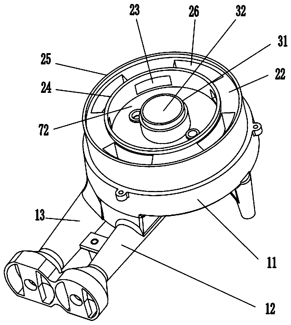
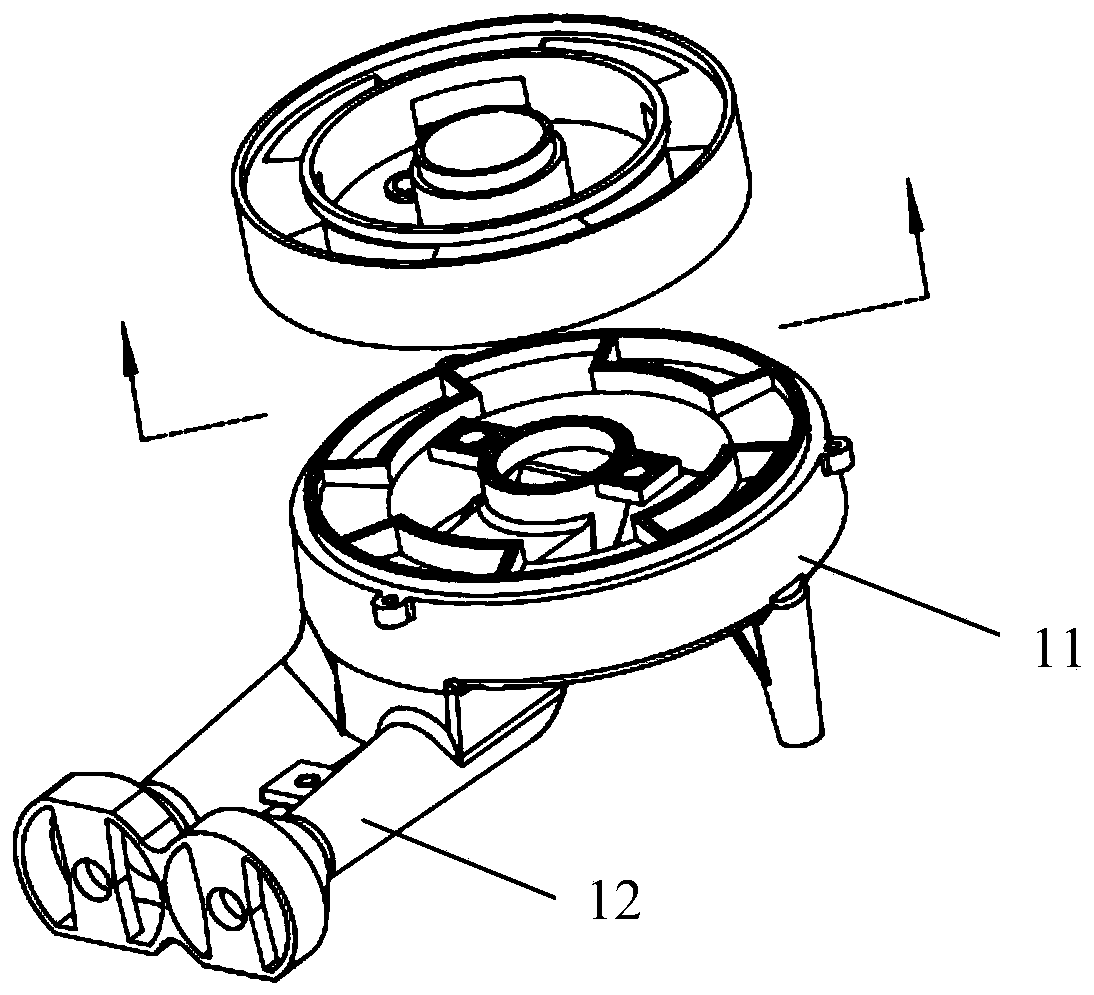
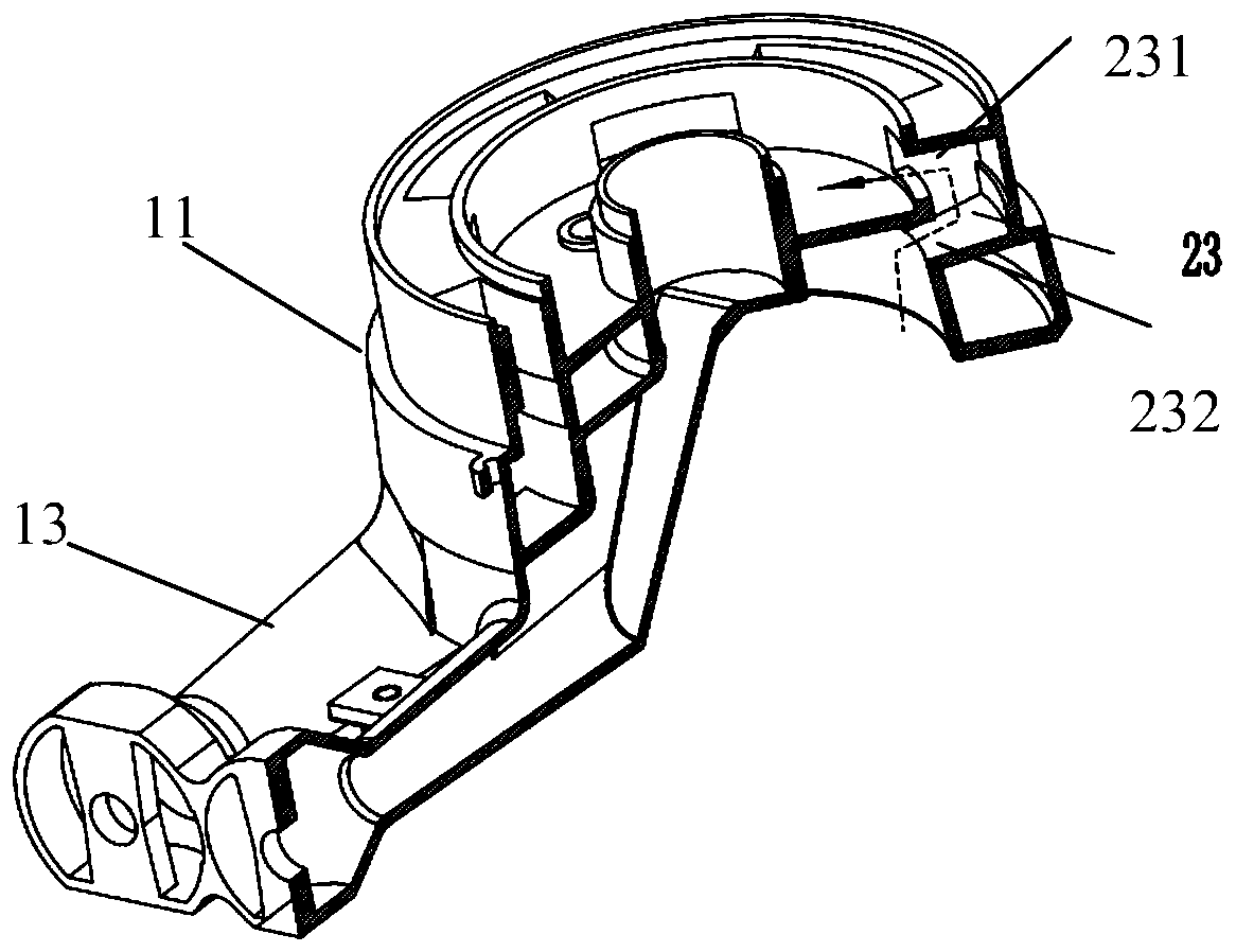
[0035] A first aspect of the present invention provides a burner head, such as figure 1 , figure 2 and image 3 As shown, the burner includes a burner body 11, wherein the burner body 11 includes an inner ring inlet chamber 72 coaxially arranged and an ou...


PUM


Abstract

The invention provides a burner head of a burner. A burner head body comprises an inner ring gas inlet cavity and an outer ring gas mixing cavity which are coaxially arranged, wherein an outer ring gas outlet channel for circulating gas required by outer ring fire combustion is arranged in the outer ring gas mixing cavity, and a secondary air supplementary channel communicating with the inner ringgas inlet cavity is also arranged on the inner wall of the outer ring gas mixing cavity and is used for providing secondary air for inner ring fire combustion. The invention also provides the burnerand a cooker comprising the burner head. According to the burner head of the burner, the secondary air supplementary channel required by an inner ring fire is in communication with the bottom of the burner head, so that the required air for sufficient combustion is more easily provided for inner ring fire combustion during combustion, and the combustion is more sufficient.

Description

technical field [0001] The invention relates to the technical field of gas stove burner equipment, in particular to a stove head for a burner, a burner and a cooker thereof. Background technique [0002] At present, most of the burners of gas stoves on the market have insufficient air supply capacity for the inner ring fire. The structure of the full-intake burner for secondary air supplement to the inner ring fire mainly includes the following types: [0003] The first one is to directly open a hole between the inner ring fire gas channel and the outer ring fire gas channel of the burner to communicate with the bottom shell of the cooker. The disadvantage of this structure is that dirt is easy to fall into the bottom shell, which is inconvenient to clean. [0004] The second is to directly open air holes in the outer ring air channel of the burner or the fire distributor as a secondary air supplementary channel. The disadvantage of this method is that high temperature and h...

Claims


Application Information

Patent Timeline
IPC IPC(8): F23D14/04F23D14/62F23D14/46F23D14/64
CPCF23D14/04F23D14/46F23D14/62F23D14/64F23D2900/14062
Inventor 周文通段聪聪刘梦茹
Owner GREE ELECTRIC APPLIANCES INC
Why Eureka
Try Eureka