
Automobile hub rim detection bench

A technology for automobile wheel hubs and testing platforms, applied in wheel testing, measuring devices, instruments, etc., can solve problems such as gauge wear, increased testing costs, affecting productivity and production efficiency, and achieve the effects of improving accuracy and reducing use and consumption

Pending Publication Date: 2020-07-28
NANJING FORESTRY UNIV
View PDF0 Cites 1 Cited by
  • Summary
  • Abstract
  • Description
  • Claims
  • Application Information

AI Technical Summary

Problems solved by technology

For the detection of these parameters, there is not only no professional testing equipment, but only gauges can be used for testing, which will cause the following problems: (1) The accuracy of manual gauge measurement is greatly affected by the subjective influence of the testing personnel, and there is no automatic testing equipment High; (2) The gauge detection is a contact detection, so it is easy to cause wear of the gauge, resulting in inaccurate detection results; (3) For different types of hubs, the rim contour shape and parameters are often different, so it needs to be customized separately The gauges matching the measured size are tested, which increases the cost of testing; and when some of the dimensions need to be modified due to design or other factors, the original gauges will no longer be applicable and need to be customized again, which will make the overall product The design and manufacturing cycle is further extended, which affects productivity and production efficiency

Method used


Image

  • Automobile hub rim detection bench
  • Automobile hub rim detection bench
  • Automobile hub rim detection bench

Examples


Embodiment Construction

[0026] The present invention will be further described below with reference to the drawings and embodiments

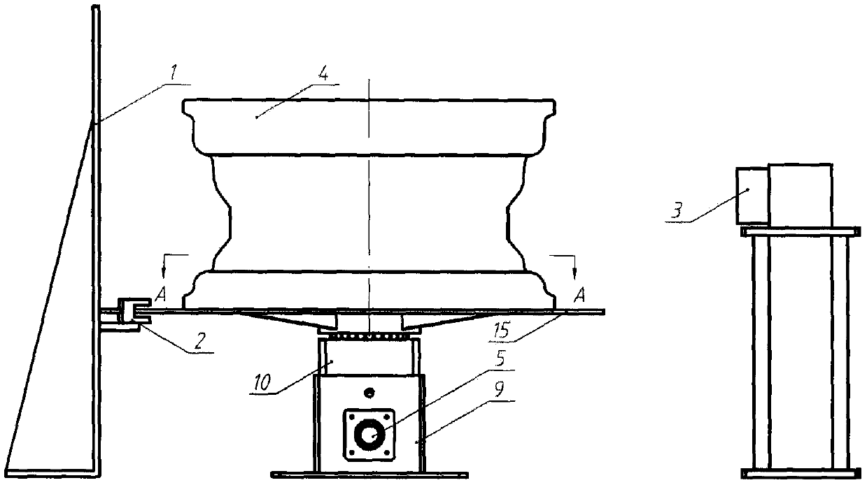
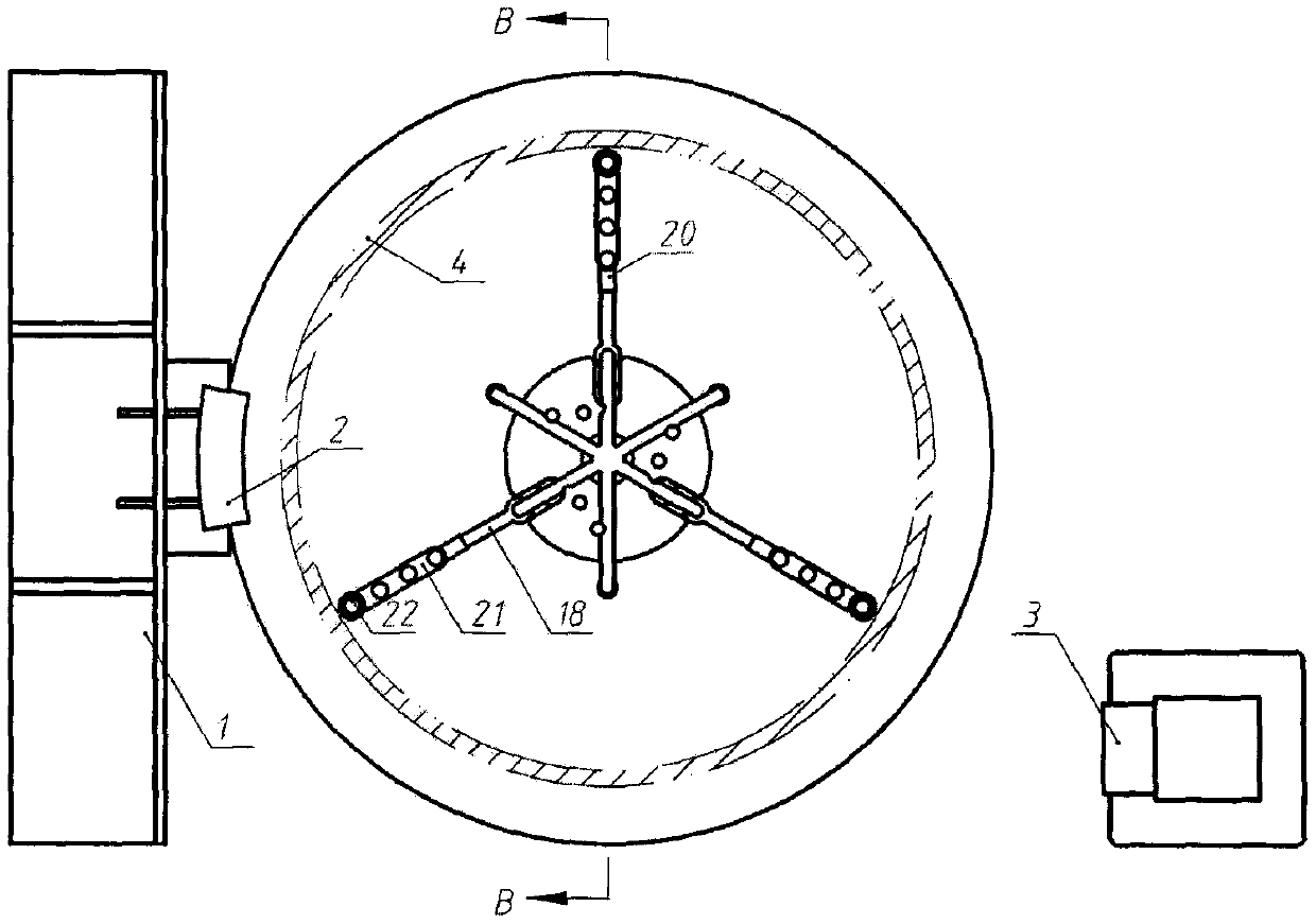
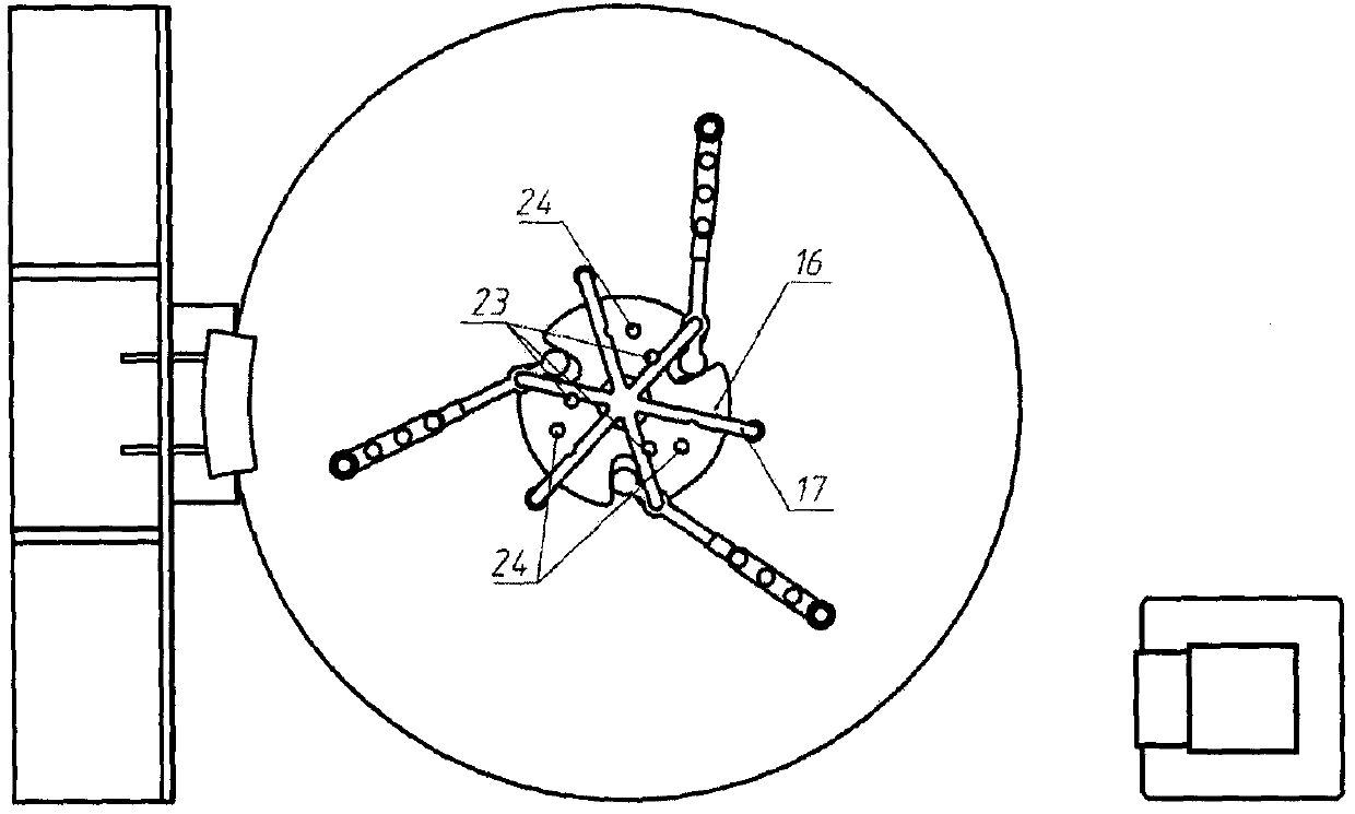
[0027] Automobile wheel rim inspection platform, including background plate 1, hydraulic caliper 2, industrial camera 3, hub 4, horizontal axis 5, bevel gear I6, vertical axis 7, bevel gear II8, horizontal axis support frame 9, longitudinal axis support frame 10, End bearing I11, end bearing II12, end bearing III13, cylindrical pin 14, platform 15, synchronous groove wheel 16, synchronous frame 17, pendulum rod 18, compression spring 19, sleeve rod 20, extension rod 21, contact wheel 22, limit Pin I23 and limit pin II24 are characterized in that the horizontal axis 5 is installed on the horizontal axis support frame 9 with a bevel gear I6 at the front end; the vertical axis 7 is installed on the vertical axis support frame 10, and the bottom end is equipped with a cone Gear II8, bevel gear I6 mesh with bevel gear II8; the horizontal axis support frame 9 and the vertical a...


PUM


Abstract

An automobile hub rim detection table is characterized in that a transverse shaft is installed on a transverse shaft supporting frame, and a bevel gear I is installed at the front end of the transverse shaft; the longitudinal shaft is mounted on the longitudinal shaft supporting frame, and a bevel gear II is mounted at the bottom end of the longitudinal shaft; the longitudinal shaft supporting frame is sequentially provided with an end face bearing I, a platform, an end face bearing II, a synchronous grooved wheel, an end face bearing III and a synchronous frame from bottom to top, and the upper end of the longitudinal shaft is matched with the synchronous grooved wheel through a profile to drive the synchronous grooved wheel to rotate. The swing rods are evenly distributed on the synchronous frame and hinged to the synchronous frame, and the rear ends of the swing rods are arranged in the synchronous pulley sliding grooves. A square groove is formed in one end of the sleeve rod, a pressure spring is arranged in the groove, and the sleeve rod sleeves the front ends of the swing rods and can freely slide on the swing rods; the extension rod is mounted at the other end of the sleeverod; the limiting pin I and the limiting pin II are respectively and uniformly distributed on the synchronous grooved wheel to limit the rotation of the synchronous grooved wheel relative to the synchronous frame; a background plate and an industrial camera are arranged on the two sides of the transverse shaft supporting frame respectively and can photograph the hub. And the size range of the hubadapted to the detection table is 16-19 inches.

Description

Technical field [0001] The invention belongs to the field of detection of automobile parts, and mainly relates to a detection device for the size of automobile wheel rims. Background technique [0002] The wheel hub is an important part of the car, which plays a bearing role in the driving of the car, and plays an important role in ensuring the performance and safety of the vehicle. On the one hand, it has to withstand the vertical gravity load of the car itself, and on the other hand, it has to withstand all kinds of dynamic load impacts such as start and stop, turning, sand and rock impact, and road inequality that the vehicle faces during driving. Therefore, the quality of the hub directly determines the safety of the vehicle. [0003] At present, the inspection of wheels mainly includes material chemical element composition inspection, mechanical performance inspection, size inspection, air tightness inspection, coating quality inspection, appearance quality inspection, etc. ...

Claims


Application Information

Patent Timeline
IPC IPC(8): G01M17/013G01B11/24
CPCG01B11/24G01M17/013
Inventor 董鹤孙见君涂桥安狄玉鹏袁帅郑伟嵇道扬牛韬
Owner NANJING FORESTRY UNIV
Learn More