
Clock processing circuit in chip debugging mode and clock processing method thereof
A technology for processing circuits and debugging modes, which is applied in electrical digital data processing, software testing/debugging, error detection/correction, etc., and can solve problems that affect the chip process and chip operating program development efficiency, so as to improve development efficiency , Optimize the effect of the development process
- Summary
- Abstract
- Description
- Claims
- Application Information
AI Technical Summary
Problems solved by technology
Method used
Image


Examples
Embodiment Construction
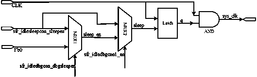
[0019] See figure 2 , The structure diagram of the clock processing circuit in the chip debugging mode implemented in the present invention. In the structure of the clock processing circuit in the chip debugging mode, the clock processing circuit includes a first selector MUX1, a second selector MUX2, a latch and a logical AND gate AND, the first selector MUX1 is connected to the second selector MUX2 , The second selector MUX2 is connected to the latch Latch, and the latch Latch is connected to the logic AND gate AND.
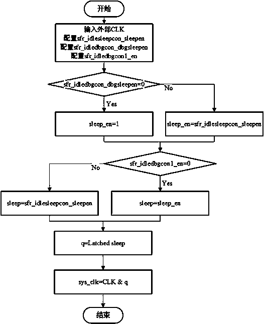
[0020] See figure 2 When the clock processing circuit works, firstly, the external clock signal CLK is given to the clock processing circuit, and the system sleep signal sfr_idlesleepcon_sleepen, the system deep sleep signal sfr_idledbgcon_dbgsleepen, and the system debug signal sfr_idledbgcon1_en are all set to 0 through the external configuration register; then, The system sleep signal sfr_idlesleepcon_sleepen is input to the first selector, and the system dee...
PUM
 Abstract
Description
Claims
Application Information