Low-vibration three-phase asynchronous motor
A three-phase asynchronous motor body technology, applied to electrical components, electromechanical devices, mechanical equipment, etc., can solve the problems of reducing the service life of three-phase asynchronous motors and damage to parts, so as to improve service life, avoid collisions, and ensure reduction shock effect
- Summary
- Abstract
- Description
- Claims
- Application Information
AI Technical Summary
Problems solved by technology
Method used
Image

Examples
Embodiment 1
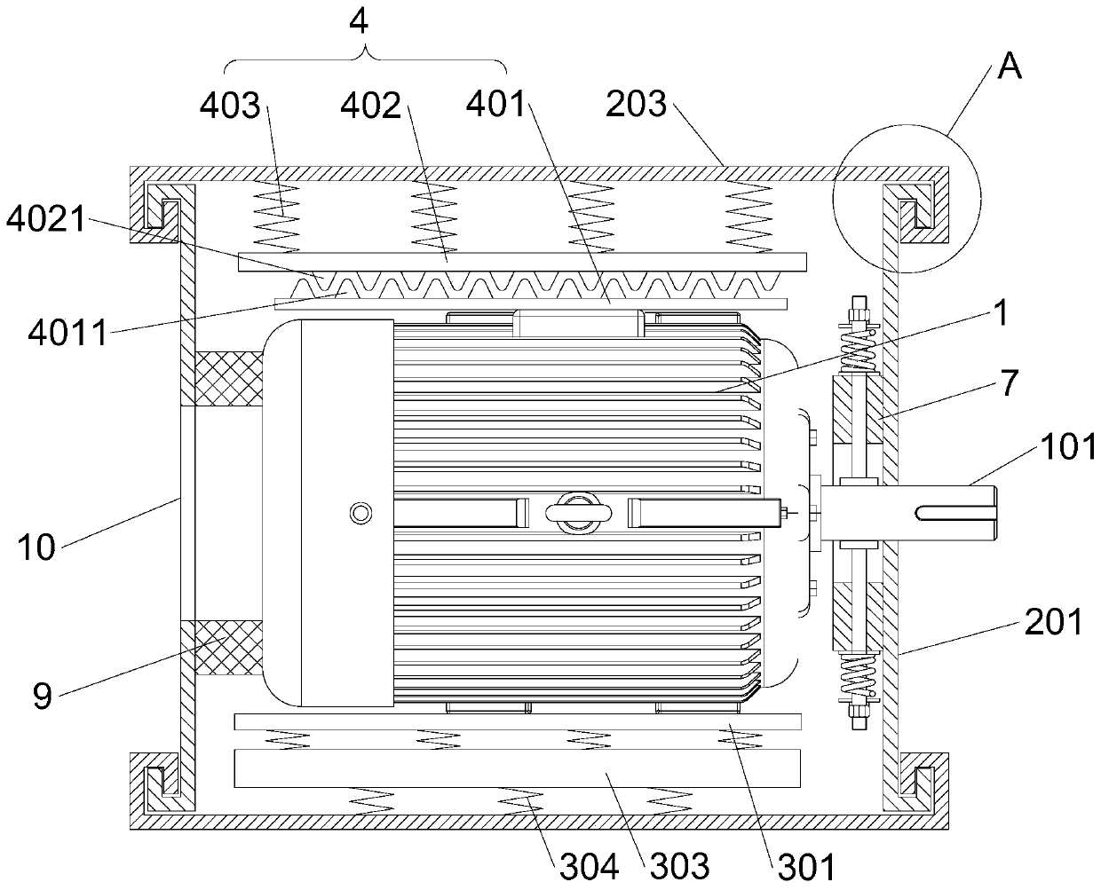
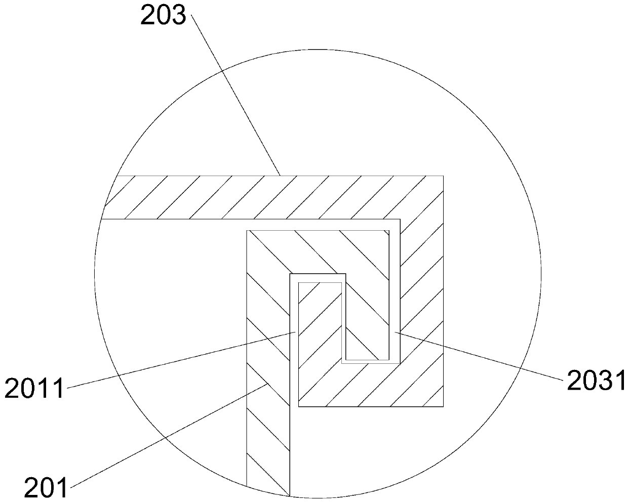
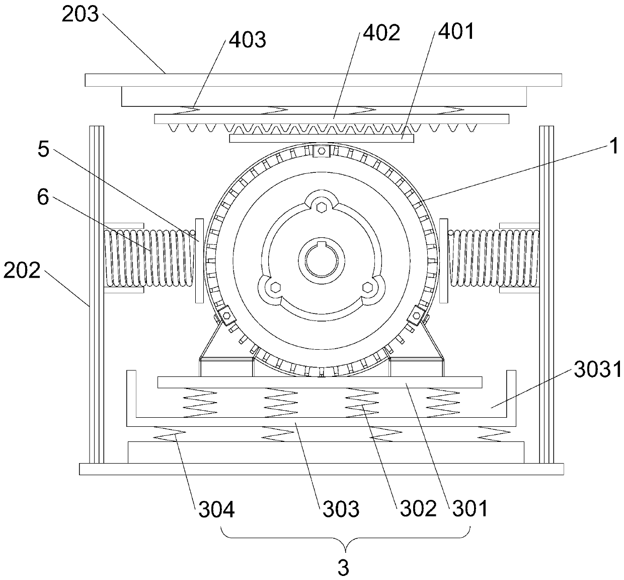
[0035]The low-vibration three-phase asynchronous motor of the present invention includes a motor body 1 and a detachable housing body 2, the motor body 1 is connected with a drive shaft 101, the motor body 1 is arranged in the housing body 2, the drive shaft 101 runs through the housing body 2, and the motor The left and right sides of the body 1 are provided with pressing plates 5, and a pressing spring 6 is arranged between the pressing plate 5 and the inner wall of the housing body 2, and a first elastic support unit 3 is arranged between the lower end of the motor body 1 and the inner wall of the housing body 2 A second elastic support unit 4 is disposed between the upper end of the motor body 1 and the inner wall of the housing body 2 , and the inner wall of the housing body 2 is provided with a positioning ring 7 located on the periphery of the drive shaft 101 .
[0036] After adopting the above-mentioned technical scheme: the present invention arranges the shell body 2 o...
Embodiment 2
[0038] This embodiment is further optimized on the basis of Embodiment 1 as follows: the first elastic support unit 3 includes a fixed plate 301, a placement plate 303, a first compression spring 302 and a second compression spring 304; the placement plate 303 is arranged on the motor Below the main body 1, the upper end of the placement plate 303 is provided with a placement groove 3031, the fixing plate 301 is arranged at the lower end of the motor body 1, the fixing plate 301 is located above the placement groove 3031, and the first compression spring 302 is located on the bottom wall of the placement groove 3031 and the fixing plate 301 Between, the lower end of the placement plate 303 and the inner wall of the housing body 2 are connected to each other through the second compression spring 304 . The second elastic support unit 4 includes a first limiting plate 401, a second limiting plate 402 and a third compression spring 403; the first limiting plate 401 is arranged on t...
Embodiment 3
[0041] This embodiment is further optimized on the basis of Embodiment 1 as follows: the first positioning protrusion 4011 and the second positioning protrusion 4021 are made of rubber, the first positioning protrusion 4011 and the second positioning protrusion 4021 The shape is conical.
[0042] After adopting the above technical solution: the first positioning protrusion 4011 and the second positioning protrusion 4021 are made of rubber, and the shape is conical, and the tips of the first positioning protrusion 4011 and the second positioning protrusion 4021 are arranged at a distance from each other . The first limiting plate 401 and the second limiting plate 402 can be backlogged to a certain extent in the vertical direction, and can have a certain misalignment correction in the horizontal direction, so as to absorb a certain vibration energy in the horizontal plane and the vertical direction.
PUM
 Abstract
Description
Claims
Application Information
 - R&D
- Intellectual Property
- Life Sciences
- Materials
- Tech Scout
- Unparalleled Data Quality
- Higher Quality Content
- 60% Fewer Hallucinations
Browse by: Latest US Patents, China's latest patents, Technical Efficacy Thesaurus, Application Domain, Technology Topic, Popular Technical Reports.
© 2025 PatSnap. All rights reserved.Legal|Privacy policy|Modern Slavery Act Transparency Statement|Sitemap|About US| Contact US: help@patsnap.com