End executor of mechanical arm of numerical control machine tool of L-shaped high pressure pipe joint

An end-effector and CNC machine tool technology, which is applied in the directions of manipulators, chucks, metal processing, etc., can solve the problems that the end-effector grasping operation is not firm enough, the service life of the end-effector is reduced, and the end-effector installation is not firm enough, etc. To achieve the effect of not easy to shake, easy to operate, and good lubrication effect

Inactive Publication Date: 2018-08-28
NANTONG AMC MACHINERY
View PDF3 Cites 1 Cited by
  • Summary
  • Abstract
  • Description
  • Claims
  • Application Information

AI Technical Summary

Problems solved by technology

[0002] The existing robot end effector refers to any tool that is connected to the edge joints of the robot and has certain functions, which may include robot grippers, robot tool quick changers, robot collision sensors, robot rotary connectors, robot pressure tools, obedience Devices, robotic spray guns, robotic deburring tools, robotic arc welding torches, robotic electric welding torches, etc., robotic end effectors are generally considered robotic peripherals, robotic accessories, robotic tools, end-of-arm tools; existing end There are certain disadvantages in the use of the actuator. The grasping operation of the traditional end effector is not firm enough, which makes the parts prone to shaking during the grasping process. The traditional end effector is prone to rust during long-term use. phenomenon, thereby reducing the service life of the end effector, the installation of the end effector is not firm enough, and it is prone to loosening, which has a certain impact on the user. Therefore, we propose a L-shaped high-pressure pipe joint CNC machine tool manipulator. end effector

Method used


Image

  • End executor of mechanical arm of numerical control machine tool of L-shaped high pressure pipe joint
  • End executor of mechanical arm of numerical control machine tool of L-shaped high pressure pipe joint
  • End executor of mechanical arm of numerical control machine tool of L-shaped high pressure pipe joint

Examples


Embodiment Construction

[0017] In order to make the technical means, creative features, goals and effects achieved by the present invention easy to understand, the present invention will be further described below in conjunction with specific embodiments.

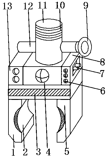
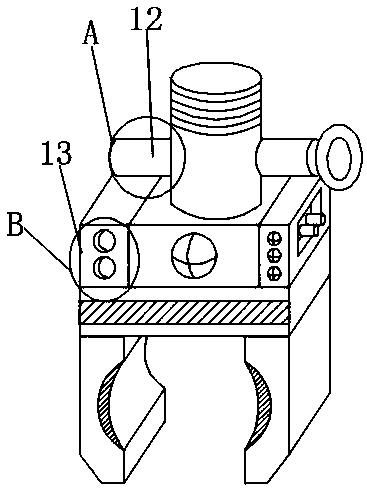
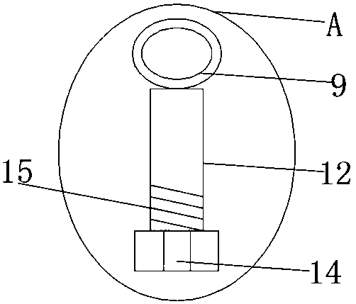
[0018] Such as Figure 1-4 As shown, an end effector of an L-shaped high-pressure pipe joint CNC machine tool manipulator includes an actuator body 4, an oil guide box 13 is fixedly installed on one side of the actuator body 4, and the other side of the actuator body 4 A control box 8 is fixedly installed on the outer surface, an indicator light 6 is fixedly installed on the outer surface of the front end of the control box 8, and a threaded bolt 11 is fixedly installed on the outer surface of the upper end of the actuator body 4, and the outer surface of the threaded bolt 11 is provided with a No. 1 fixed thread 10. A safety bolt 12 is fixedly installed on the inner surface of the threaded bolt 11 close to the bottom of the No. 1 fixed thread 10,...


PUM


Abstract

The invention discloses an end executor of a mechanical arm of a numerical control machine tool of an L-shaped high pressure pipe joint. The end executor comprises a main executor body, an oil guide box is fixedly arranged on the outer surface of one side of the main executor body, and a control cabinet is fixedly arranged on the outer surface of the other side of the main executor body. An indicator lamp is fixedly arranged on the outer surface of the front end of the control cabinet, and a threaded bolt is fixedly arranged on the outer surface of the upper end of the main executor body. A fixed screw thread I is arranged on the outer surface of the threaded bolt, and a safety bolt is fixedly arranged at the lower part, close to the fixed screw thread I, of the inner surface of the threaded bolt. A rotary buckle is fixedly arranged on the outer surface of one end of the safety bolt. The end executor is provided with the oil guide box, the safety bolt and a skid-proof rubber mat, thusthe executor has the advantages of convenience in lubrication, firm mounting, high safety performance and good application prospect.

Description

technical field [0001] The invention relates to the field of actuator equipment, in particular to an end effector of an L-shaped high-pressure pipe joint numerical control machine tool manipulator. Background technique [0002] The existing robot end effector refers to any tool that is connected to the edge joints of the robot and has certain functions, which may include robot grippers, robot tool quick changers, robot collision sensors, robot rotary connectors, robot pressure tools, obedience Devices, robotic spray guns, robotic deburring tools, robotic arc welding torches, robotic electric welding torches, etc., robotic end effectors are generally considered robotic peripherals, robotic accessories, robotic tools, end-of-arm tools; existing end There are certain disadvantages in the use of the actuator. The grasping operation of the traditional end effector is not firm enough, which makes the parts prone to shaking during the grasping process. The traditional end effector ...

Claims


Application Information

Patent Timeline
Patent Type & Authority Applications(China)
IPC IPC(8): B25J15/00B25J19/00B23Q7/04
CPCB25J15/00B23Q7/043B25J19/0062
Inventor 戚顺平凌圣军梁松千冯克明唐玉芝
Owner NANTONG AMC MACHINERY
Why Eureka
Try Eureka