
Ultralow-temperature integrated direct-current bias device

A DC bias, integrated technology, applied in electrical components, chassis/cabinet/drawer parts, electrical equipment shell/cabinet/drawer, etc. Inconvenient maintenance and other problems, to achieve the effect of ensuring work stability, ensuring stability, improving installation efficiency and installation accuracy

Pending Publication Date: 2020-07-28
NANJING HMC SYST CO LTD +1
View PDF0 Cites 0 Cited by
  • Summary
  • Abstract
  • Description
  • Claims
  • Application Information

AI Technical Summary

Problems solved by technology

[0003] At this stage, the processing of multiple active devices that require a DC bias is generally to treat different devices separately, that is, to add a DC bias to each device to provide stable working conditions for the device. However, this This separate treatment method will cause the final equipment system to be too large in size, complicated in wiring, and very inconvenient to install, use or maintain.

Method used


Image

  • Ultralow-temperature integrated direct-current bias device
  • Ultralow-temperature integrated direct-current bias device
  • Ultralow-temperature integrated direct-current bias device

Examples


Embodiment Construction

[0028] The present invention will be further described below in conjunction with the accompanying drawings. The following examples are only used to illustrate the technical solution of the present invention more clearly, but not to limit the protection scope of the present invention.

[0029] In describing the present invention, it should be understood that the terms "center", "longitudinal", "transverse", "upper", "lower", "front", "rear", "left", "right", " The orientations or positional relationships indicated by "vertical", "horizontal", "top", "bottom", "inner" and "outer" are based on the orientations or positional relationships shown in the drawings, and are only for the convenience of describing the present invention and Simplified descriptions, rather than indicating or implying that the device or element referred to must have a particular orientation, be constructed and operate in a particular orientation, and thus should not be construed as limiting the invention. ...


PUM


Abstract

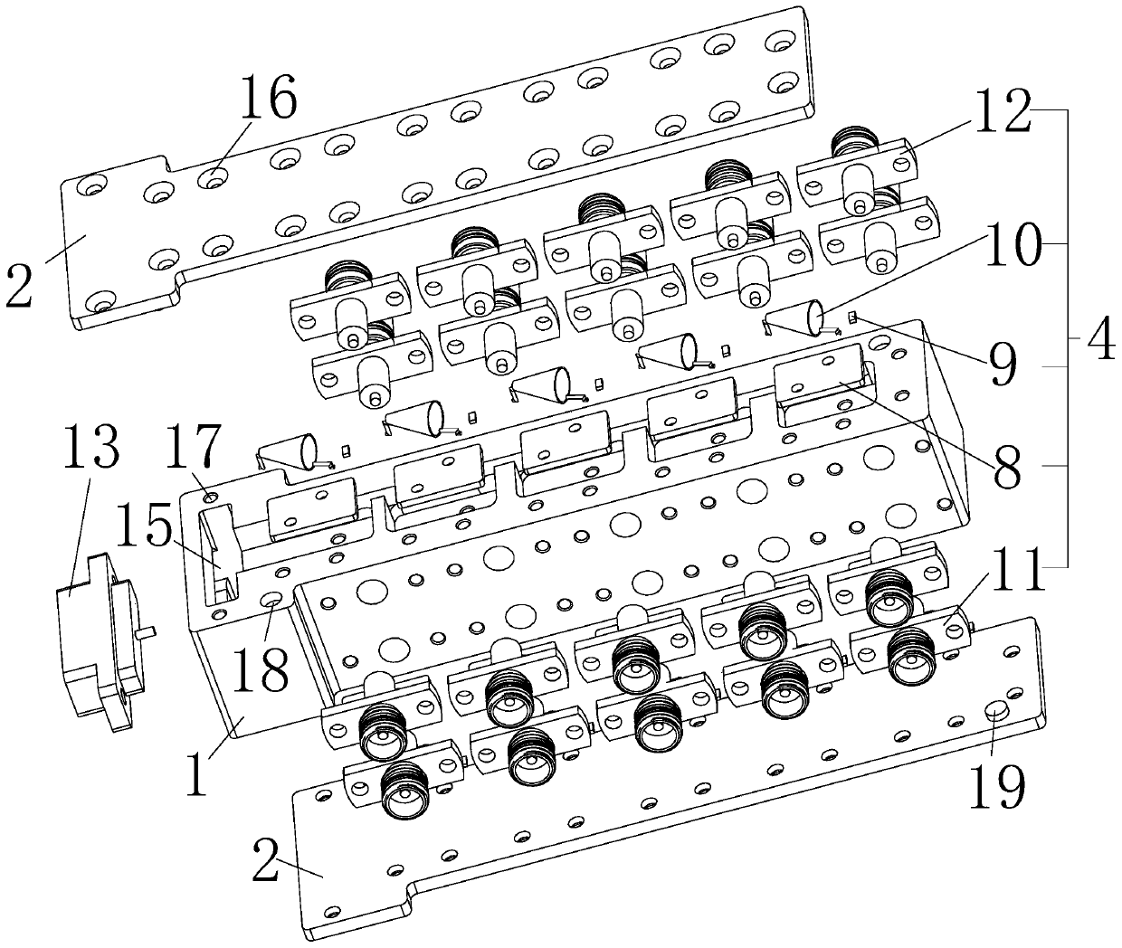
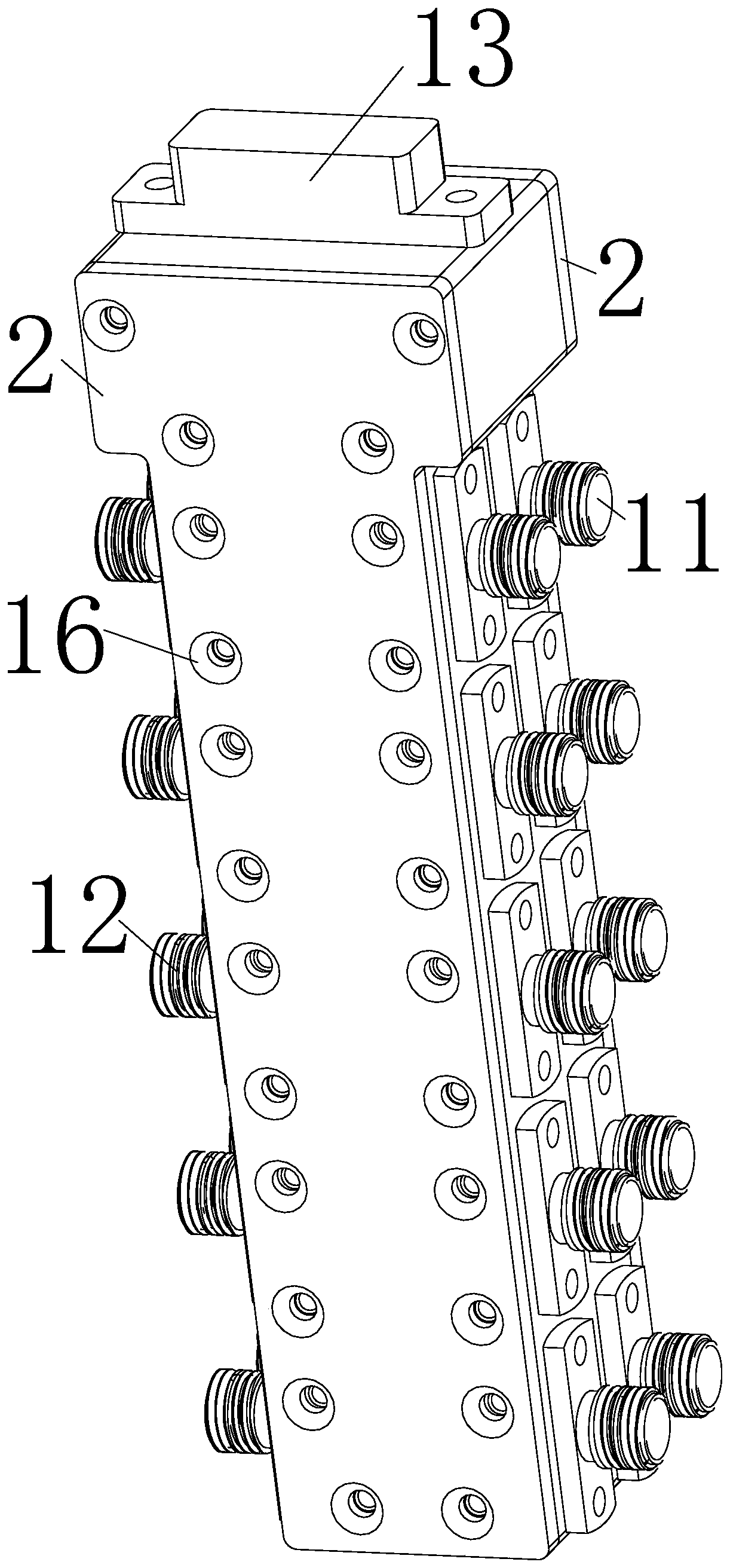
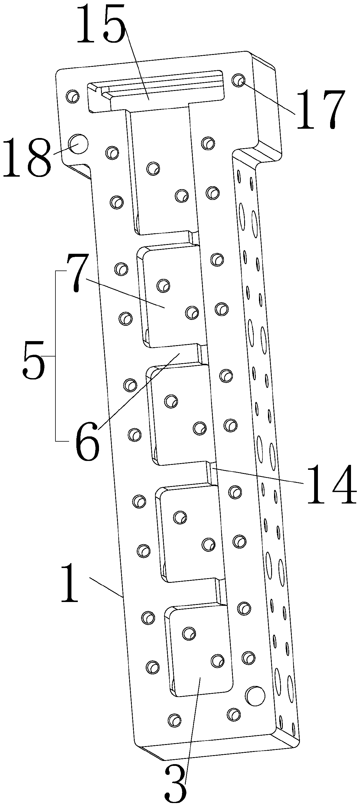
The invention relates to an ultralow-temperature integrated direct-current bias device and belongs to the technical field of an electronic circuit. The bias device comprises a hollow chamber, over plates which are arranged at an upper end and a lower end of the cavity in a covering mode and detachably connected with the cavity, cavities formed in the chamber, and direct current bias assemblies which are arranged in the cavities respectively, wherein the cavities are separated by partition plate assemblies, the partition plate assembly comprises a vertical partition plate perpendicular to the cover plate and a layered partition plate parallel to the cover plate, the layered partition plate is fixedly connected with the interior of the chamber, and the vertical partition plate is perpendicularly and fixedly connected with the layered partition plate. The ultralow-temperature integrated direct-current bias device provided by the invention is advantaged in that the volume occupation is reduced, wiring complexity is reduced, and installation, use and maintenance are more convenient.

Description

technical field [0001] The invention relates to an ultra-low temperature integrated DC bias device, which belongs to the technical field of electronic circuits. Background technique [0002] DC Biasers are used to provide bias current or voltage to active devices such as amplifiers, laser diodes, photodiodes, or optical modulators while allowing high-speed, ultra-wideband signals to pass through with minimal signal attenuation. These biasers feature low insertion loss, very wide frequency response, and exceptional time-domain performance; [0003] At this stage, the processing of multiple active devices that require a DC bias is generally to treat different devices separately, that is, to add a DC bias to each device to provide stable working conditions for the device. However, this This separate treatment method will cause the final equipment system to be too large, the wiring is complicated, and it is very inconvenient to install, use or maintain. Contents of the invent...

Claims


Application Information

Patent Timeline
Patent Type & Authority Applications(China)
IPC IPC(8): H05K5/00H05K5/02H05K5/03
CPCH05K5/00H05K5/0069H05K5/02H05K5/0217H05K5/0247H05K5/03
Inventor 陆聆唐荣刘银银刘晨曦
Owner NANJING HMC SYST CO LTD
Learn More