Multiple geometry and multiple material insulated components

A heat insulation space and accessories technology, applied in the direction of heat insulation containers, lighting and heating equipment, pipeline protection through heat insulation, etc., can solve the problem of not providing heat insulation sheaths and other problems

Inactive Publication Date: 2020-07-28
CONCEPT GRP LLC
View PDF23 Cites 0 Cited by
  • Summary
  • Abstract
  • Description
  • Claims
  • Application Information

AI Technical Summary

Problems solved by technology

The prior art does not provide the ability to manufacture such insulating sheaths, particularly those that enclose curved or irregularly shaped lumens

Method used


Image

  • Multiple geometry and multiple material insulated components
  • Multiple geometry and multiple material insulated components
  • Multiple geometry and multiple material insulated components

Examples


Embodiment 1

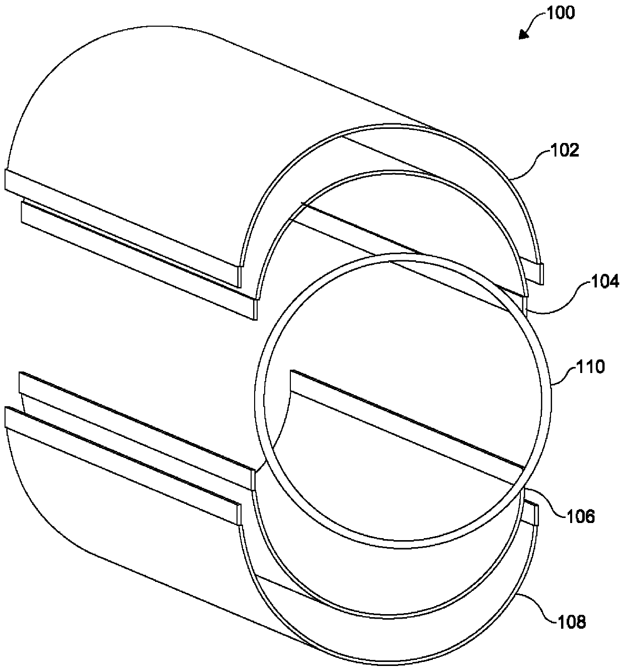
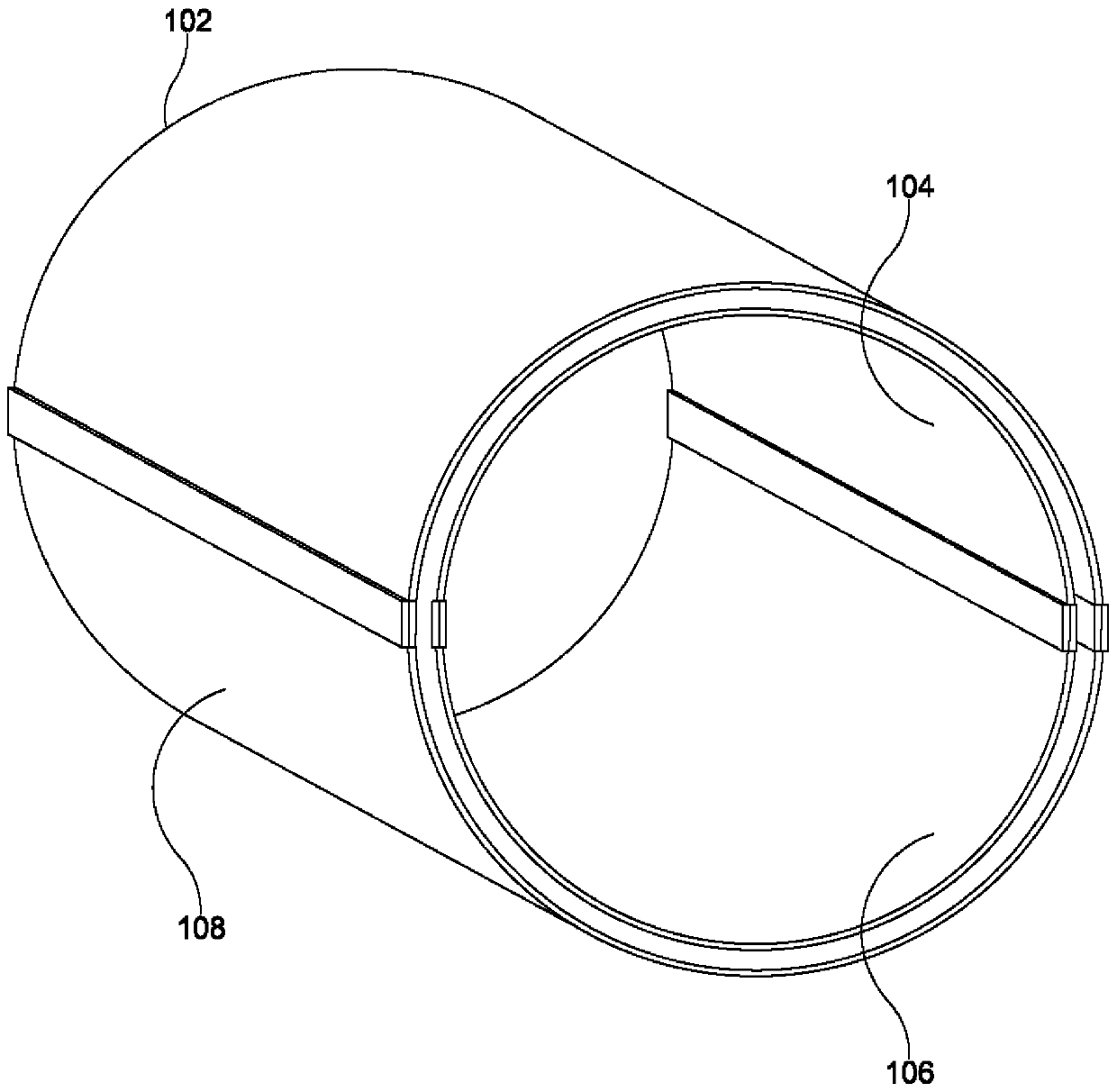
[0170] Example 1. An insulated pipe comprising: (a) an outer tube having a distal end and a proximal end, the outer tube also comprising a first corrugated region having a length and including a length extending from the distal end of the outer tube to the outer tube a plurality of corrugations extending along the proximal end of the outer tube; an inner tube disposed within the outer tube, the inner tube having a distal end and a proximal end, the inner tube defining a lumen; the inner tube and the outer tube at a joint, optionally the inner tube are sealed to each other at distal ends thereof, the seal defining a pressure-reduced sealed insulating region between the outer tube and the inner tube, the inner tube and the outer tube are sealed to each other such that the length of the first corrugated region of the outer tube increases in response to temperature or or (b) an outer tube, the outer tube has a distal end and a proximal end, an inner tube is disposed within the out...

Embodiment 2

[0174] Example 2. The insulated duct of claim 1, wherein the sealed insulation area is defined within a range from about 10 -2 Torr to about 10 -9 pressures in the Torr range, for example, about 10 -3 Torr, 10 -4 Torr, 10 -5 Torr, 10 -6 Torr, 10 -7 Torr, 10 -8 Torr or even about 10 -9 Torr and all intermediate values.

Embodiment 3

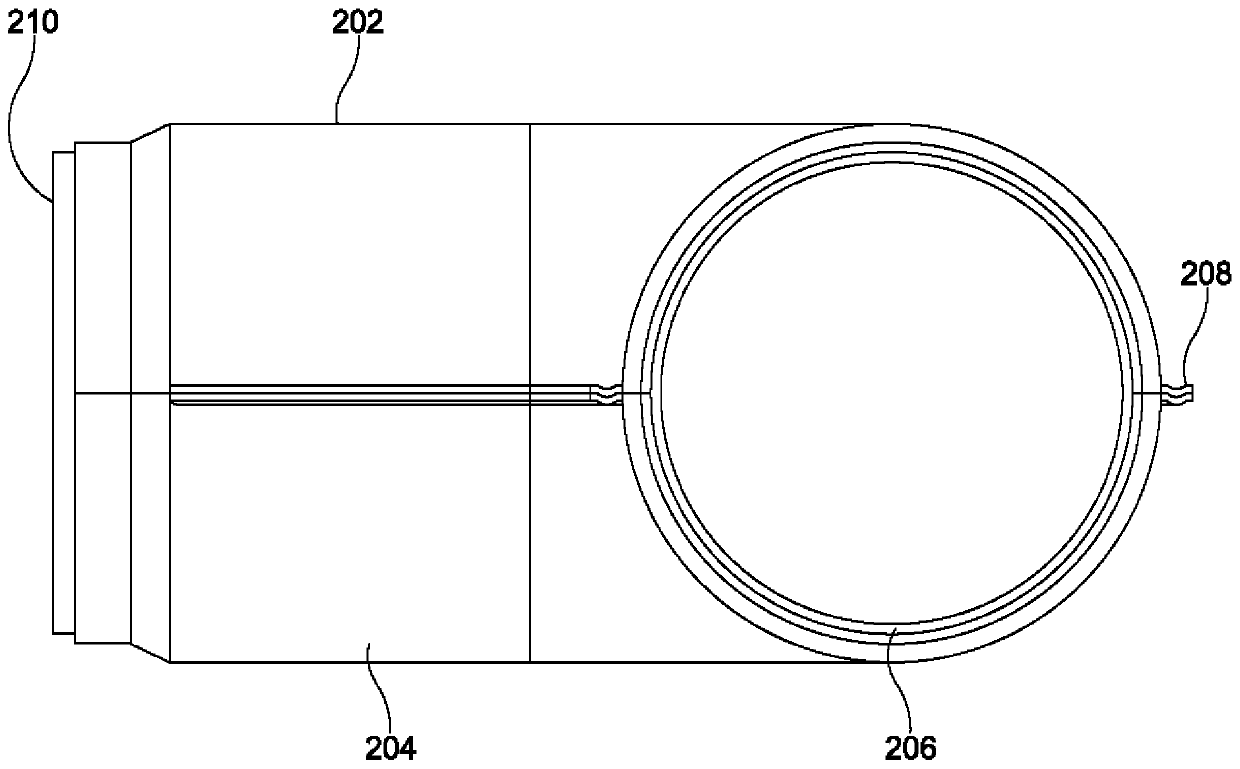
[0175] Example 3. An insulated duct according to any one of claims 1-2, wherein the joint comprises (a) a first vent in communication with the sealed insulating area to provide a path for gas molecules to escape from the sealed insulating area, section a vent is sealable for maintaining a reduced pressure within the first insulated space after gas molecules are evacuated through the first vent, and (b) sealing the first insulated space at the first vent The first seal.


PUM


Abstract

The present disclosure provides insulated components that include corrugated regions, which corrugated regions may reside on inner tubes, outer tubes, or both. The present disclosure also provides insulated components that may achieve straight, curved, or other variable geometries.

Description

[0001] related application [0002] This application claims priority and benefit to the following patent applications: U.S. Patent Application No. 62 / 550,182 "Clamshell Configured Insulators" (filed August 25, 2017); U.S. Patent Application No. 62 / 550,200, " Flexible Vacuum Insulated Components" (filed August 25, 2017); U.S. Patent Application No. 62 / 562,543, "Multiple Geometry Insulated Conduits" (September 25, 2017) filed); U.S. Patent Application No. 62 / 567,361, "Insulated Components Comprising Different Thermal Expansion Materials" (filed October 3, 2017); and U.S. Patent Application No. 62 / 594,180, "Multiple Multiple Geometry Insulated Conduits" (submitted December 4, 2017). All of the foregoing applications are hereby incorporated by reference in their entirety for any and all purposes. technical field [0003] The present disclosure relates to the field of vacuum insulation articles. Background technique [0004] A variety of high-performance applications require p...

Claims


Application Information

Patent Timeline
Patent Type & Authority Applications(China)
IPC IPC(8): F16L59/06A47J41/02B65D81/38F16L9/14F16L11/11F16L11/12F16L11/15
CPCA47J41/02F16L59/024F16L59/065F16L59/182F16L59/22
Inventor A·H·瑞德小D·H·瑞德S·拉德哈格里希南
Owner CONCEPT GRP LLC
Why Eureka
Try Eureka