Detecting and sorting mechanism for inferior-quality bottle cap gaskets
A detection mechanism and a technology for covering gaskets, which are applied in sorting and other directions, can solve problems such as low work efficiency, incomplete coverage of gaskets, time-consuming and labor-intensive problems, and achieve the effect of improving work efficiency
- Summary
- Abstract
- Description
- Claims
- Application Information
AI Technical Summary
Problems solved by technology
Method used
Image

Examples
Embodiment Construction
[0023] The following will clearly and completely describe the technical solutions in the embodiments of the present invention with reference to the accompanying drawings in the embodiments of the present invention. Obviously, the described embodiments are only some, not all, embodiments of the present invention. Based on the embodiments of the present invention, all other embodiments obtained by persons of ordinary skill in the art without making creative efforts belong to the protection scope of the present invention.
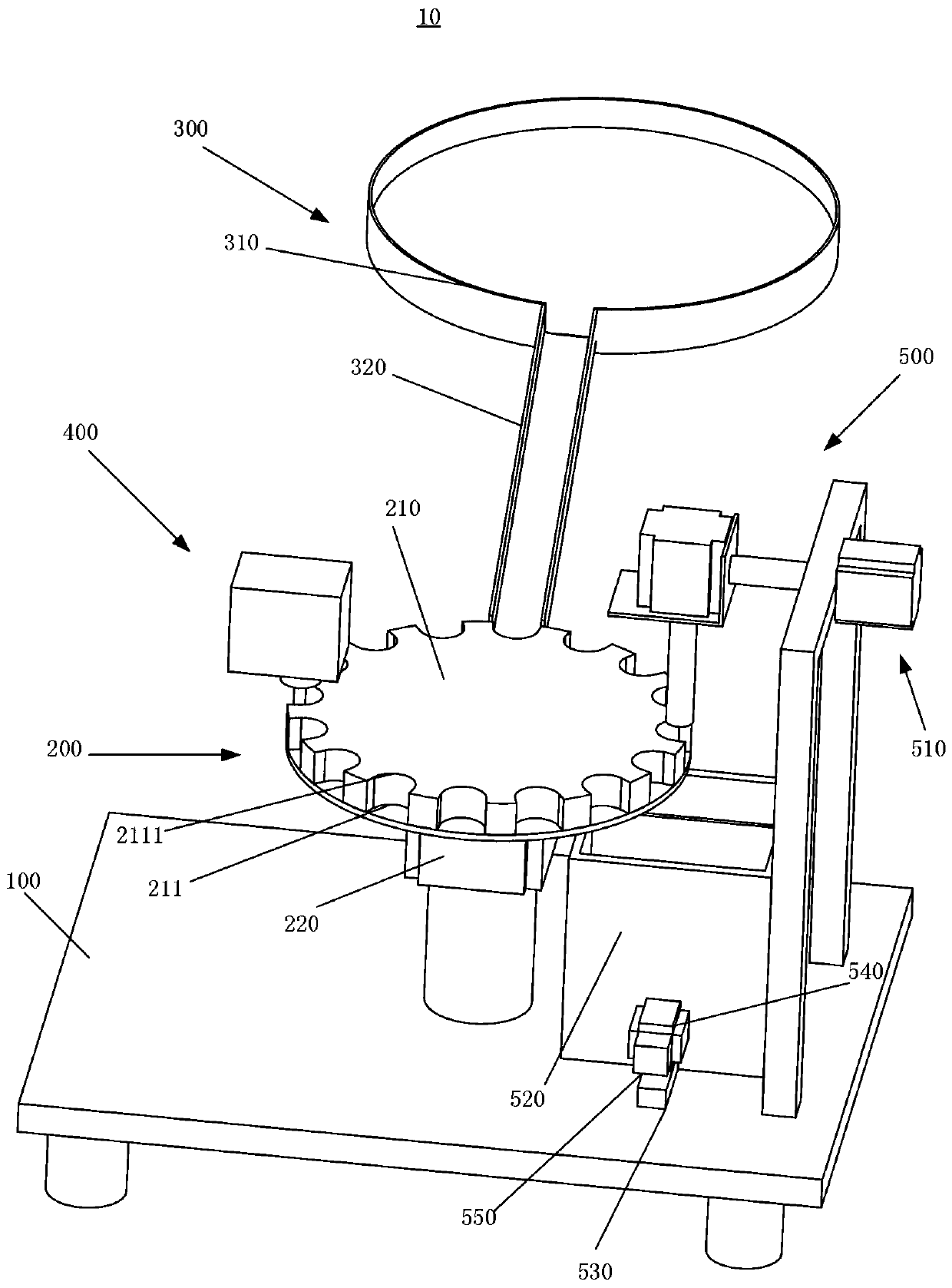
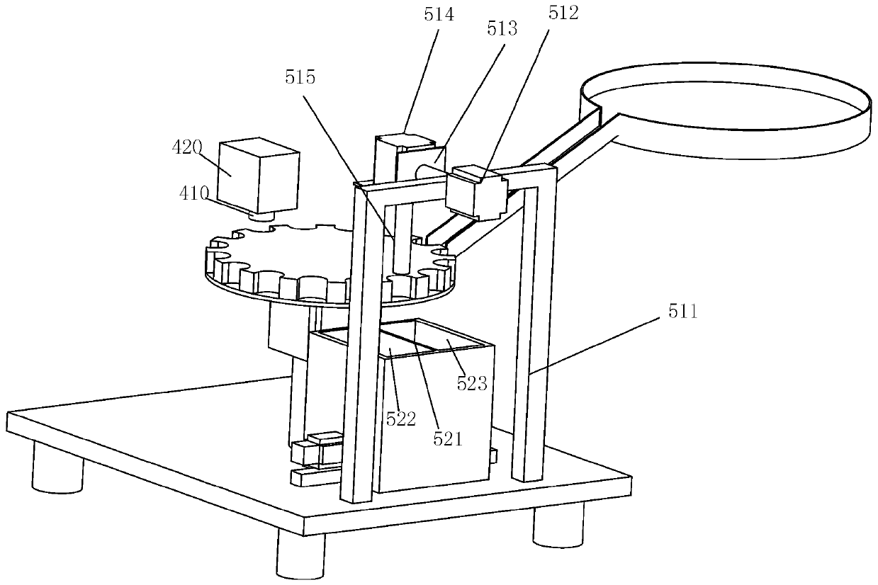
[0024] Such as figure 1 and figure 2 As shown, it is a defective bottle cap gasket detection and sorting mechanism 10 according to an embodiment of the present invention, including: a workbench 100, a rotating mechanism 200, a feeding mechanism 300, a detection mechanism 400 and a sorting mechanism 500;
[0025] The rotating mechanism 200 is arranged on the workbench 100, and the rotating mechanism 200 includes a rotating disc 210 and a rotating motor 220, t...
PUM
 Abstract
Description
Claims
Application Information
PatSnap Eureka turns technology decisions into work you can execute. Powered by our Innovation Knowledge Graph, it runs expert workflows across engineering, life sciences, materials and intellectual property. Get your review-ready output in minutes.


