A stainless steel alloy flange manufacturing and processing machine

A technology of processing machinery and alloy method, which is applied in the direction of manufacturing tools, metal processing equipment, grinding workpiece supports, etc., can solve the problems of circumferential rotation of flanges, low processing efficiency, poor grinding effect, etc., and increase the tight fit degree, increase the grinding effect, increase the effect of stability

Active Publication Date: 2021-05-11
盐城斯天康精密制造有限公司
View PDF7 Cites 1 Cited by
  • Summary
  • Abstract
  • Description
  • Claims
  • Application Information

AI Technical Summary

Problems solved by technology

[0004] 1. Before removing the bolt hole burrs on the flange, when the flange is installed on the fixture of the processing equipment, the stability is poor when locked, which will easily cause the flange to rotate in the circumferential direction during grinding, resulting in poor grinding effect, etc. question;
[0005] 2. The deburring tool installed on the rotary processing equipment needs to slowly position the flange hole before processing the flange hole each time. The positioning efficiency is low, and the burr on the inner wall of the flange hole can only be removed at a time, and the processing efficiency is low;
[0006] 3. Ordinary deburring tools can only remove the burrs on the inner wall of the bolt hole on the flange, while the burrs on the upper end surface of the bolt hole need to be processed again by other deburring equipment, and the processing efficiency is low

Method used


Image

  • A stainless steel alloy flange manufacturing and processing machine
  • A stainless steel alloy flange manufacturing and processing machine
  • A stainless steel alloy flange manufacturing and processing machine

Examples


Embodiment Construction

[0027] In order to make the technical means, creative features, goals and effects achieved by the present invention easy to understand, the present invention will be further described below in conjunction with specific illustrations. It should be noted that, in the case of no conflict, the embodiments in the present application and the features in the embodiments can be combined with each other.

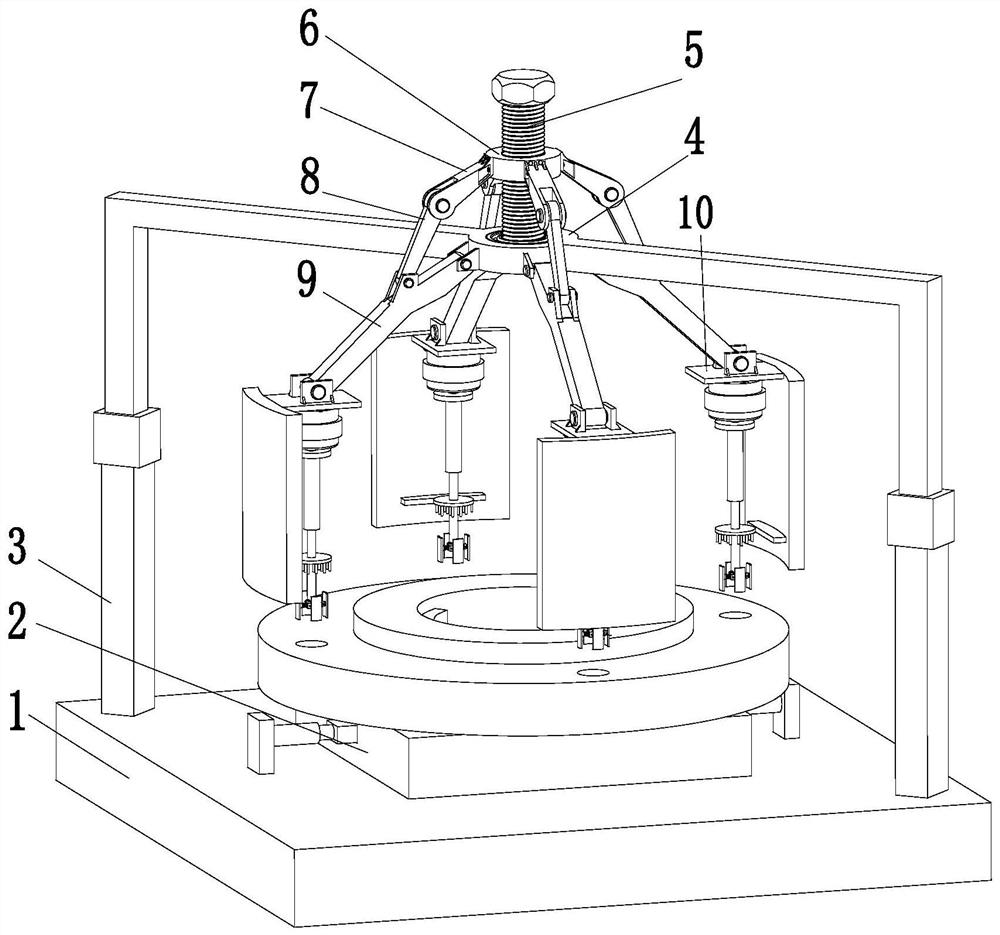
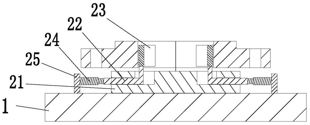
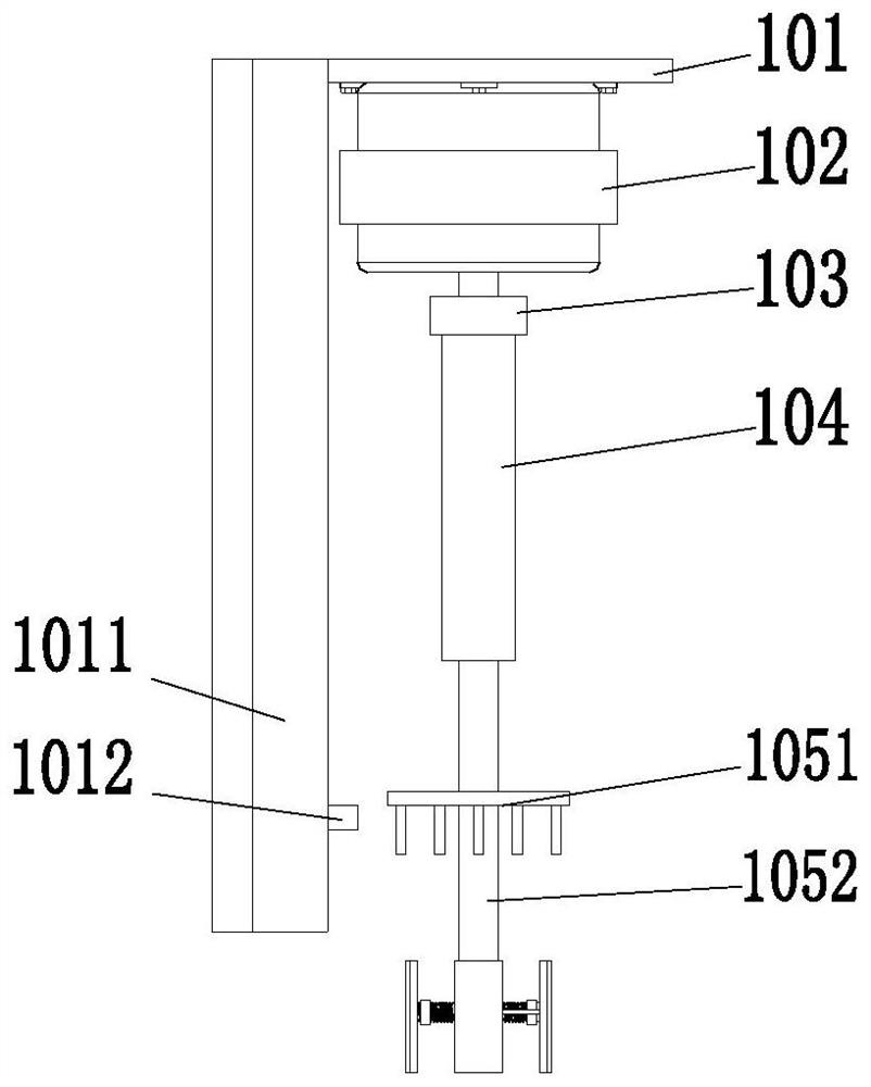
[0028] Such as Figure 1 to Figure 4 As shown, it includes a base 1, a limit mechanism 2, an L-shaped rod 3, a circular seat 4, a bolt 5, an annular block 6, an adjusting arm 7, a connecting arm 8, a driven arm 9 and a grinding mechanism 10. The upper part of the base 1 The limit mechanism 2 is installed on the end face, the L-shaped rod 3 is installed on the right front and the left rear of the upper end face of the base 1, and the circular seat 4 is installed between the inner side of the upper end of the L-shaped rod 3, and the circular seat 4 is located at the bottom of the base ...


PUM


Abstract

The invention relates to a stainless steel alloy flange manufacturing and processing machine, comprising a base, a limit mechanism, an L-shaped rod, a circular seat, a bolt, an annular block, an adjusting arm, a connecting arm, a driven arm and a grinding mechanism, and the upper end surface of the base The limit mechanism is installed on the top, and L-shaped rods are installed on the right front and left rear of the upper end surface of the base. A circular seat is installed between the inner side of the upper end of the L-shaped rod. The circular seat is connected with the lower end of the bolt through a bearing, and the middle of the bolt is threaded. A ring block is connected in a matching manner. Four adjusting arms are symmetrically installed on the outer surface of the ring block. The lower end of each adjusting arm is connected to the upper middle part of the slave arm through the connecting arm, and the lower end of the slave arm is installed through a hinge. There is a grinding mechanism. The present invention can solve the existing problem of deburring the bolt holes on the flange: the fixture of the processing equipment has poor locking effect on the flange; the processing equipment can only process one bolt hole at a time, and the burr on the upper end surface of the bolt hole needs other Equipment secondary processing.

Description

technical field [0001] The invention relates to the field of flange manufacturing and processing, in particular to a stainless steel alloy flange manufacturing and processing machine. Background technique [0002] Flange is otherwise known as flange flange or flange. Flanges are parts that connect shafts to shafts and are used for the connection between pipe ends. Several fixed holes are opened around the flanges for adding flange pads between the two flanges. The holes are fastened together to complete the connection. After drilling the bolt holes on the flange during the flange production process, burrs will be generated on the inner wall of the hole and the upper end surface. The bolt holes can be used normally after deburring. . [0003] For the deburring step in the flange production process, the deburring tool is generally installed on rotary processing equipment such as drilling machines, milling machines, and lathes for grinding and deburring. The bolt holes on the...

Claims


Application Information

Patent Timeline
Patent Type & Authority Patents(China)
IPC IPC(8): B24B19/00B24B41/06B24B47/22B24B41/04B24B47/12B24B47/20
CPCB24B19/00B24B41/04B24B41/06B24B47/12B24B47/20B24B47/22
Inventor 陈成任赵玉鸿
Owner 盐城斯天康精密制造有限公司
Why Eureka
Try Eureka