
Surface rust removal equipment for mechanical part machining

A technology for mechanical parts and equipment, which is applied in the field of surface rust removal equipment for mechanical parts processing, can solve the problems of incomplete rust removal, inability to grind and remove rust on the side of the plate, and rust, and achieve the effect of improving the effect of rust removal

Active Publication Date: 2020-07-31
黄石弘诚机械有限公司
View PDF7 Cites 9 Cited by
  • Summary
  • Abstract
  • Description
  • Claims
  • Application Information

AI Technical Summary

Problems solved by technology

[0007] In addition to the two board surfaces, the rectangular board also includes four sides. When the board is rusted, the side will also be rusted, especially for the thicker board. The above two Both patents can derust the surface of the rectangular plate, but they can only polish the two sides of the plate, and cannot polish and derust the side of the plate. The derusting is not comprehensive, resulting in the need for additional labor on the opposite side in the follow-up while grinding

Method used


Image

  • Surface rust removal equipment for mechanical part machining
  • Surface rust removal equipment for mechanical part machining
  • Surface rust removal equipment for mechanical part machining

Examples


Embodiment 1

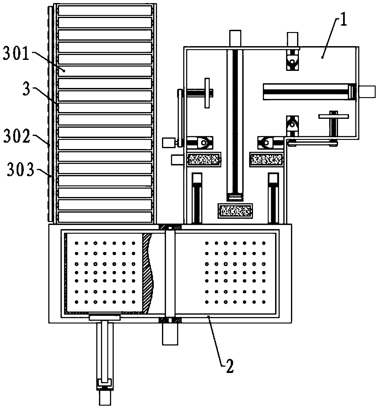
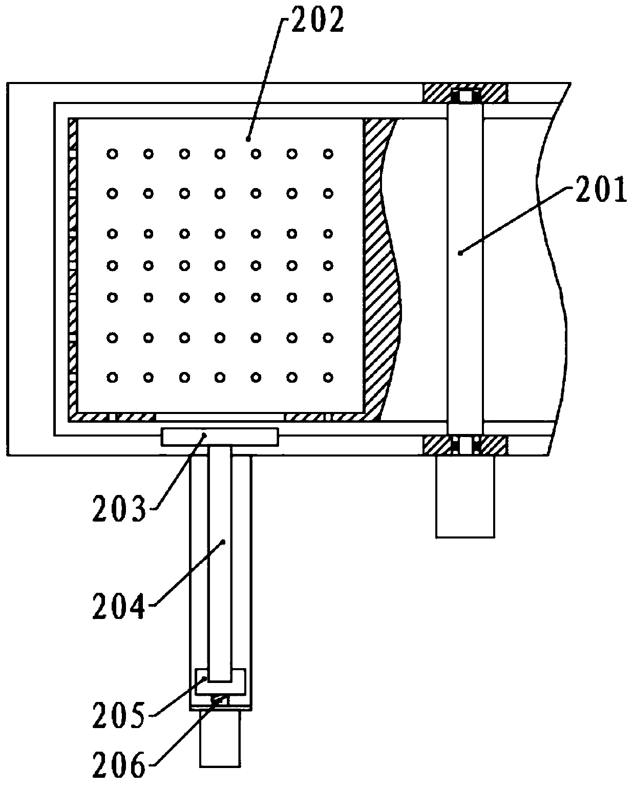
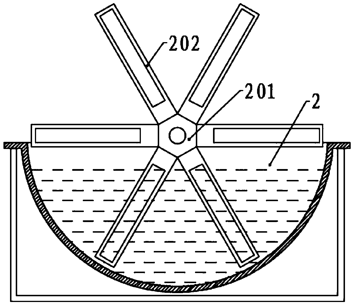
[0043] Please refer to the accompanying drawings, the present invention provides a technical solution: a surface derusting equipment for mechanical parts processing, comprising a soaking tank 2, the rear side of the soaking tank 2 is provided with a blanking mechanism and a feeding mechanism, and the soaking tank 2 is provided with There is a rotating mechanism, and the rotating mechanism includes a rotating column 201 that is rotatably connected to the middle of the soaking tank 2 tops. One end of the rotating column 201 is connected with a motor, and a plurality of rotating plates 202 are evenly fixed on the rotating column 201 along the circumferential direction. The rotating plates 202 There is a plate groove in the center, and a plurality of through holes are arranged on the side wall of the plate groove, the rear side end of the plate groove is set as an open shape, and a push port is provided in the middle of the other end, and the top of the soaking tank 2 corresponds to...

Embodiment 2

[0063] The structure of this embodiment is basically the same as that of Embodiment 1, the difference is that a limit plate 705 is provided on one side of the first side grinding assembly and the second side grinding assembly, and the limit plate 705 is connected to the top of the fixed table 1. The surface is slidingly connected, and the fixed table 1 is correspondingly provided with an adjusting groove, which is parallel to the corresponding moving groove, and the bottom surface of the limit plate 705 is fixed with an adjusting block, which is slidably connected in the adjusting groove, and is rotatably connected with an adjusting Screw rod, one end of the adjusting screw rod protrudes from the adjusting groove, and a pulley is fixed on the corresponding first screw rod 703, and the pulley is fixed on the corresponding first screw rod 703, and the two pulleys are connected by a transmission belt.

[0064] When the first screw rod 703 is rotated by the motor, the moving block ...

Embodiment 3

[0066] The structure of this embodiment is basically the same as that of Embodiment 2, the difference is that a ring gear 207 is jointly fixed between the outer ends of a plurality of rotating plates 202, and the bottom of the soaking tank 2 is evenly connected along the direction of the arc surface and is rotationally connected with a plurality of On the rotating shaft, a plurality of toggle plates 209 are evenly fixed along the circumferential direction, and a rotating gear 208 is fixed on one side of the rotating shaft, and the plurality of rotating gears 208 are all meshed with the ring gear 207 .

[0067] When the rotating mechanism drives the plates to rotate intermittently in the soaking tank 2, the ring gear 207 drives the rotating gear 208 to rotate, and the rotating gear 208 drives the rotating shaft and the toggle plate 209 to rotate, thereby generating agitation at the bottom of the soaking tank 2, making the soaking tank 2 The liquid is in full contact with the sur...


PUM


Abstract

The invention relates to surface rust removal equipment for mechanical part machining in the technical field of machine part machining. The surface rust removal equipment for mechanical part machiningcomprises a soaking tank, a discharging mechanism and a feeding mechanism, a rotating mechanism is arranged in the soaking tank, a pushing assembly is correspondingly arranged on the rear side of therotating mechanism, the feeding mechanism comprises a fixing table, and a first side edge polishing assembly, a second side edge polishing assembly, a lower polishing assembly and an upper polishingassembly are arranged on the fixing table. According to the surface rust removal equipment, through the first side edge polishing assembly, the second side edge polishing assembly, the upper polishingassembly and the lower polishing assembly, comprehensive polishing of the surfaces of plates is achieved, and the effect of rust removal liquid in the soaking tank is used in cooperation to further improve the rust removal effect; through forward rotation and reverse rotation of a first lead screw, a second lead screw and a third lead screw and cooperation of clamping plates capable of rotating and returning on a plurality of sliding blocks, intermittent conveying of the plates is achieved, intermittent movement of the plates is matched with intermittent movement of the rotating mechanism, and therefore physical rust removal and chemical rust removal are achieved in the moving and rotating processes of the plates.

Description

technical field [0001] The invention relates to the technical field of mechanical parts processing, in particular to a surface derusting device for processing mechanical parts. Background technique [0002] Mechanical parts, also known as mechanical components, are the basic components of machinery. They are inseparable individual parts that make up machinery and machines. They are also the basic units in the mechanical manufacturing process. The manufacturing process generally does not require assembly processes, such as shaft sleeves. , Bearing bushes, nuts, crankshafts, blades, gears, cams, connecting rod bodies, connecting rod heads, etc. Mechanical parts are not only a subject of research and design of mechanical basic parts in various equipment, but also a general term for parts and components. [0003] Parts are generally not used immediately after production and processing. Therefore, they need to be stored in the warehouse for a long period of time. For some parts ...

Claims


Application Information

Patent Timeline
Patent Type & Authority Applications(China)
IPC IPC(8): B24B27/033B24B7/17B24B41/00B24B47/22B24B41/02
CPCB24B7/17B24B27/033B24B41/005B24B41/02B24B47/22
Inventor 徐丰詹习生高红亮朱军于俊
Owner 黄石弘诚机械有限公司
Learn More