
Remote diagnosis and remote control marking device and circuit for trolley slide wire of self-propelled trolley

A technology of a bicycle and a marking device, which is applied in the field of remote diagnosis, can solve the problems of inability to apply the inspection of the sliding contact line of the bicycle, not suitable for the installation and use of the bicycle, and no marking function, so as to eliminate the later maintenance cost and reduce the energy consumption. , easy-to-use effects

Pending Publication Date: 2020-07-31
王旭峰
View PDF0 Cites 0 Cited by
  • Summary
  • Abstract
  • Description
  • Claims
  • Application Information

AI Technical Summary

Problems solved by technology

Since there are other self-propelled trolleys on the aluminum rails, about 5 meters of trolley lines can be inspected each time, requiring inspectors to frequently replace the self-propelled trolleys, which poses a great safety hazard
[0005] High-altitude high-voltage cable inspection robot, because it is used for the inspection of high-altitude high-voltage cables, cannot be applied to the inspection of trolley trolley lines
The reasons are as follows: 1. It is specially designed for high-voltage cables and is not suitable for installation and use on the aluminum rail of self-propelled trolleys. 2. It needs battery power supply and needs to be disassembled and charged frequently. 3. The operation is cumbersome. 4. There is no marking function. 5. The manufacturing cost is high. 6. It needs to be equipped with additional power device, and the working power consumption is high

Method used


Image

  • Remote diagnosis and remote control marking device and circuit for trolley slide wire of self-propelled trolley
  • Remote diagnosis and remote control marking device and circuit for trolley slide wire of self-propelled trolley
  • Remote diagnosis and remote control marking device and circuit for trolley slide wire of self-propelled trolley

Examples


Embodiment Construction

[0026] The present invention will be further described and explained below in conjunction with the accompanying drawings.

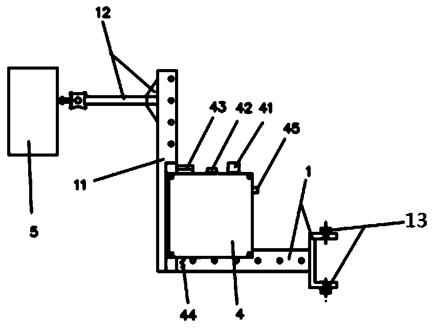
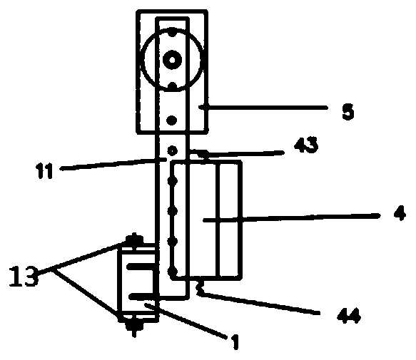
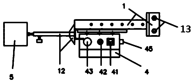
[0027] Such as Figure 1-7 Shown: a self-propelled trolley trolley remote diagnosis remote control marking device, including a remote inspection device and a marking device; the remote inspection device includes a main bracket 1, an adjustment bracket 11, and an electrical control box 4; the main The bracket 1 is fixed to the self-propelled trolley frame through the fixing bolt A13, the main bracket 1 and the adjustment bracket 11 are connected and fixed by the bolt B, the adjustment plate is connected between the main bracket 1 and the adjustment bracket 11, and the main bracket 1 1. The angle between the adjustment brackets 11 is adjusted by the bolt holes on the adjustment plate; the camera bracket 12 is fixed on the end of the adjustment bracket 11, the wireless camera 5 is installed on the top of the camera bracket 12, and the electrical control box ...


PUM


Abstract

The invention relates to the technical field of remote diagnosis, and particularly relates to a remote diagnosis and remote control marking device and circuit for a trolley slide wire of a self-propelled trolley. According to the main technical scheme, the remote diagnosis and remote control marking device comprises a remote inspection device and a marking device body; the remote inspection devicecomprises a main support, an adjusting support and an electric control box; and the main support is fixed to a self-propelled trolley frame through a fixing bolt A, the main support and the adjustingsupport are connected and fixed through a fixing bolt B, an adjusting plate is connected between the main support and the adjusting support, and the angle between the main support and the adjusting support is adjusted through bolt hole positions in the adjusting plate. According to the remote diagnosis and remote control marking device and circuit, an electromagnet is additionally arranged to serve as a marking system of a power source, a remote control mode is adopted for control, the remote control distance is long, the anti-interference capability is high, and the requirement for use in aworkshop is met. And the marking points can be conveniently and uniformly maintained in the later period. The cost is low, the safety is improved, and potential safety hazards caused by high-altitudemaintenance operation are avoided.

Description

technical field [0001] The invention relates to a self-propelled trolley trolley line remote diagnosis remote control marking device and a circuit, belonging to the technical field of remote diagnosis. Background technique [0002] The self-propelled trolley for engine transfer is 8 meters above the ground, and the aluminum rail is hung under the steel grid frame of the factory building. The self-propelled trolley is suspended on the aluminum rail and obtains electric energy from the sliding contact line inside the aluminum rail to realize walking and the lifting action of the electric hoist on the trolley. The trolley line on the inside of the aluminum rail is deformed due to wear and tear after long-term use, which requires regular inspection and diagnosis. There are usually two ways to check and diagnose trolley lines: [0003] One is to use a 3-meter ladder to place it on a protective net 5 meters above the ground and 3 meters high from the trolley line after the power ...

Claims


Application Information

Patent Timeline
Patent Type & Authority Applications(China)
IPC IPC(8): B66C13/12B66C13/40B66C13/48B66C15/00
CPCB66C13/12B66C13/40B66C13/48B66C15/00
Inventor 王旭峰郑尧鹿新弟李程韩冰姚有鹏
Owner 王旭峰
Learn More