Alignment marking method and manufacturing method of mask plate

A technology of alignment mark and production method, applied in the field of mask production and alignment mark, can solve the problems affecting the pixel position accuracy and influence of the mask, so as to improve the actual evaporation accuracy, reduce waste, and improve the accuracy of the alignment mark. The effect of bit precision

Inactive Publication Date: 2020-07-31
WUHAN CHINA STAR OPTOELECTRONICS SEMICON DISPLAY TECH CO LTD
View PDF6 Cites 2 Cited by
  • Summary
  • Abstract
  • Description
  • Claims
  • Application Information

AI Technical Summary

Problems solved by technology

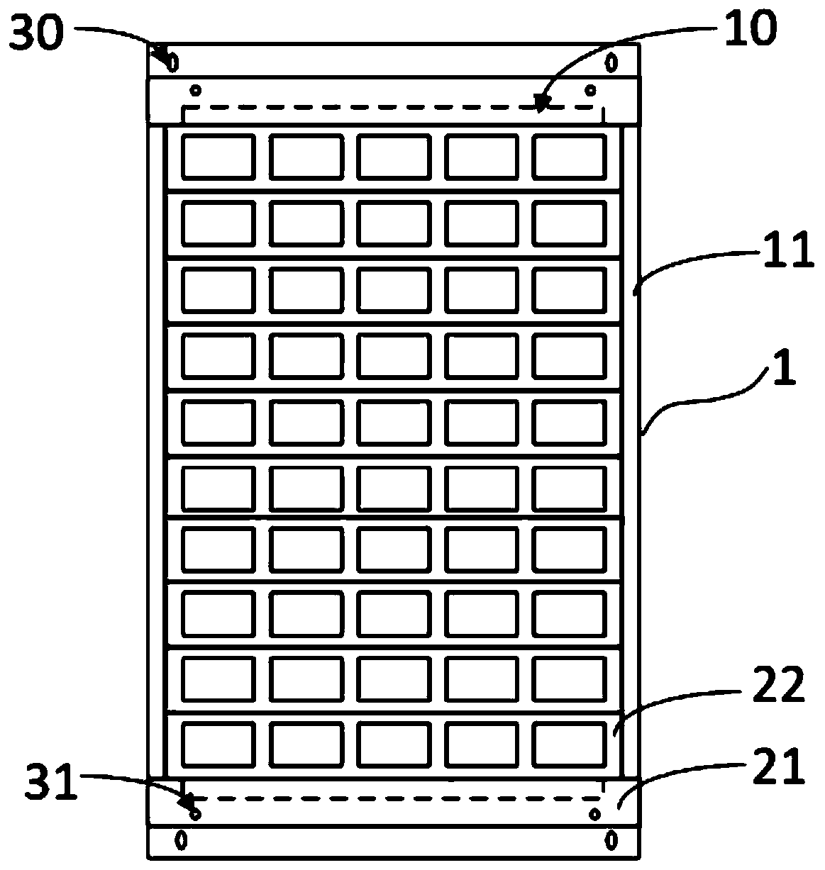
The shape and position of the original alignment mark 31 of the alignment mask 21 will also be affected

Method used


Image

  • Alignment marking method and manufacturing method of mask plate
  • Alignment marking method and manufacturing method of mask plate
  • Alignment marking method and manufacturing method of mask plate

Examples


Embodiment Construction

[0033] The technical solutions in the embodiments of the present invention will be clearly and completely described below in conjunction with the drawings in the embodiments of the present invention. Obviously, the described embodiments are only a part of the embodiments of the present invention, rather than all the embodiments. Based on the embodiments of the present invention, all other embodiments obtained by those skilled in the art without creative work shall fall within the protection scope of the present invention.

[0034] In the description of the present invention, it should be understood that the terms "center", "longitudinal", "transverse", "length", "width", "thickness", "upper", "lower", "front", " "Back", "Left", "Right", "Vertical", "Horizontal", "Top", "Bottom", "Inner", "Outer", "Clockwise", "Counterclockwise" and other directions or The positional relationship is based on the position or positional relationship shown in the drawings, and is only for the conven...


PUM


Abstract

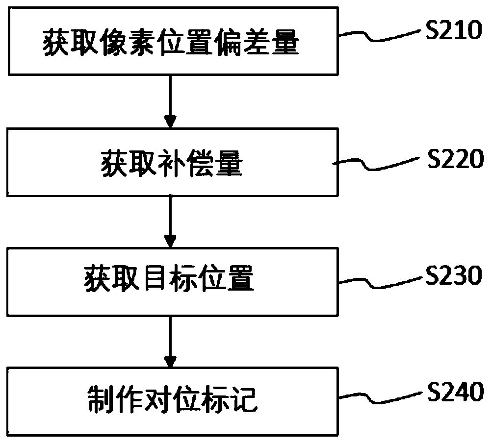
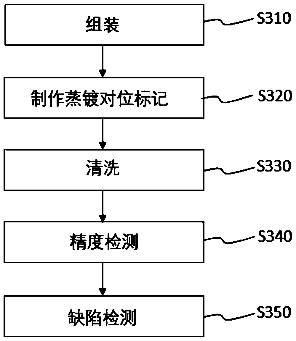
The invention discloses an alignment marking method and a manufacturing method of a mask plate. The alignment marking method comprises the steps that (1) the deviation value of pixel positions is acquired; (2) the compensation dosage is acquired; and (3) offset compensation is carried out. By means of the alignment marking manufacturing method, compensation to offset of the pixel positions of themask plate can be completed; and by means of the manufacturing method of the mask plate, the alignment marking method is adopted for completing compensation to offset of the pixel positions in the production process of manufacturing the mask plate, and then the offset compensation step in the evaporation technological process can be omitted.

Description

Technical field [0001] The present invention relates to the technical field of display device manufacturing, in particular to a method for alignment marks and a method for manufacturing a mask. Background technique [0002] In the manufacturing process of the OLED display panel, the organic light-emitting material layer is generally formed by vacuum evaporation coating of the organic material. Among them, for an OLED that emits light independently by RGB sub-pixels, since each RGB sub-pixel uses different organic light-emitting materials, the organic light-emitting layers of the RGB sub-pixels need to be vapor-deposited separately. In the above evaporation process, a fine metal mask (Fine Metal Mask, referred to as: FMM) is generally used to control the coating position of the organic material on the substrate (Glass), and then the corresponding organic material is evaporated in each sub-pixel area in turn . [0003] Therefore, the matching accuracy of the FMM and the substrate d...

Claims


Application Information

Patent Timeline
IPC IPC(8): C23C14/04C23C14/24C23C14/12H01L51/56
CPCC23C14/042C23C14/24C23C14/12H10K71/164H10K71/166
Inventor 刘志乔
Owner WUHAN CHINA STAR OPTOELECTRONICS SEMICON DISPLAY TECH CO LTD
Why Eureka
Try Eureka