

A coating jig and coating method
A fixture and mounting position technology, applied in sputtering plating, vacuum evaporation plating, ion implantation plating, etc., can solve problems such as poor contact of electronic component pins
- Summary
- Abstract
- Description
- Claims
- Application Information
AI Technical Summary
Problems solved by technology
Method used
Image

Examples
Embodiment Construction
[0031] The technical solutions in the embodiments of the present application will be described below with reference to the accompanying drawings in the embodiments of the present application.
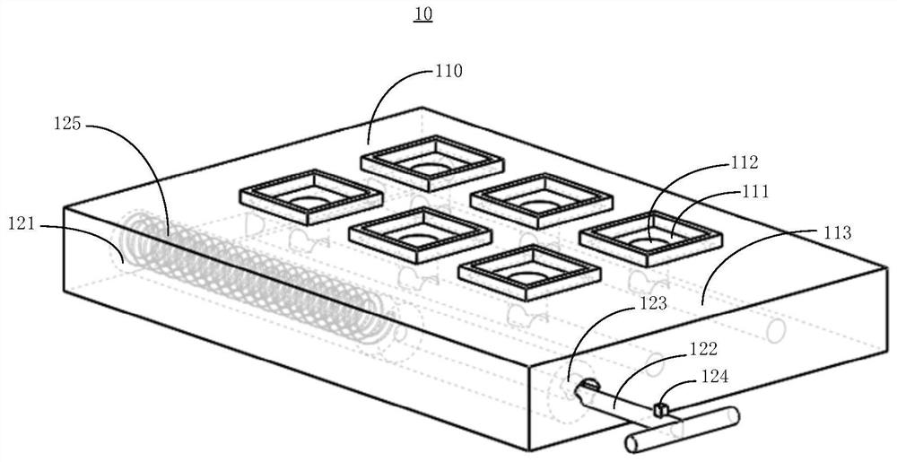
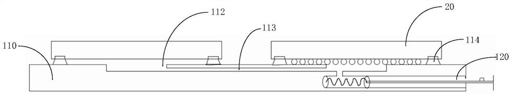
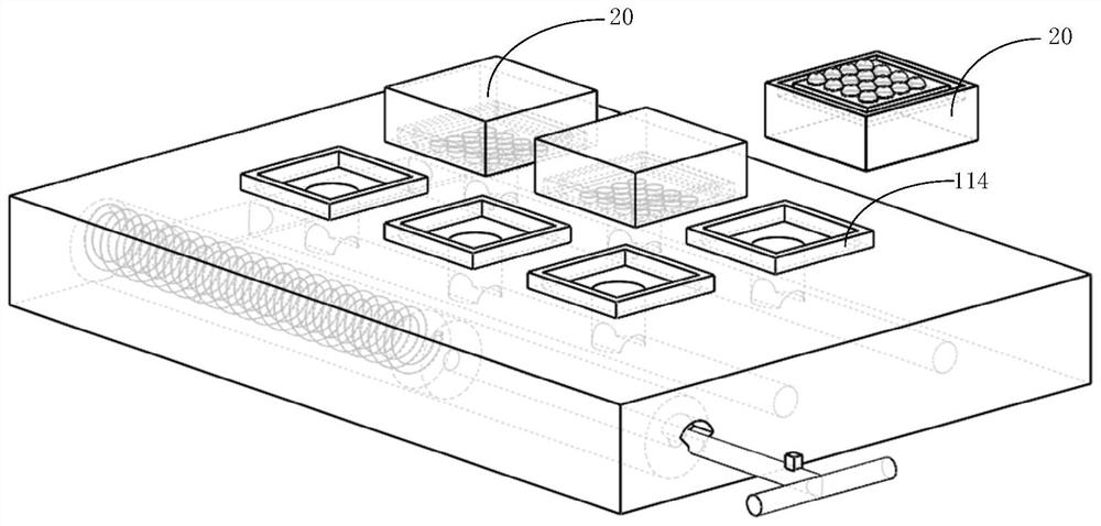
[0032] figure 1 A schematic diagram of a three-dimensional structure of a coating jig 10 provided in the embodiment of the present application, figure 2 A schematic cross-sectional structure diagram of a coating jig 10 provided in an embodiment of the present application, the coating jig 10 is used for placing the components 20 to be coated for coating, including: a jig body 110 and a pressure control device 120; The surface of the main body 110 is provided with at least one mounting position 111 , the mounting position 111 is used to place the components 20 to be coated, and the mounting position 111 is provided with a through hole 112 ; the fixture body 110 is provided with a ventilation channel inside 113, the first end of the ventilation channel 113 is communicated with the throug...
PUM
 Abstract
Description
Claims
Application Information