Supercharge Your Innovation With Domain-Expert AI Agents!

A remote on-duty management system for bank intelligent trunk cabinets

A management system and intelligent technology, applied in safes, instruments, electromagnetic radiation induction, etc., can solve the problems of uncontrollable timeliness, high escort costs, and poor safety.

Active Publication Date: 2021-06-04
山东银保智能科技有限公司
View PDF0 Cites 0 Cited by
  • Summary
  • Abstract
  • Description
  • Claims
  • Application Information

AI Technical Summary

Problems solved by technology

At present, the tail boxes of banks are usually picked up by escort companies every day, which requires professionals and professional equipment. The timeliness is uncontrollable, the safety is poor, and the cost of escort is also high.

Method used


Image

  • A remote on-duty management system for bank intelligent trunk cabinets
  • A remote on-duty management system for bank intelligent trunk cabinets
  • A remote on-duty management system for bank intelligent trunk cabinets

Examples


no. 1 approach

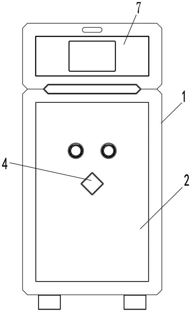
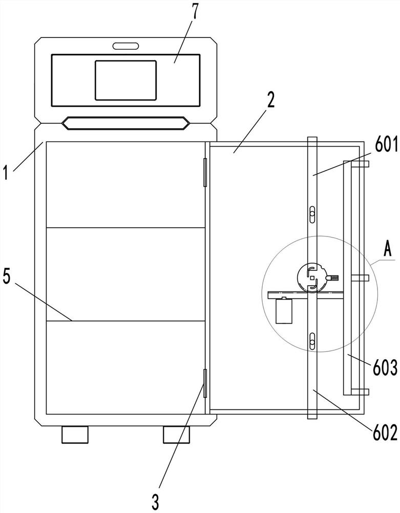
[0040] Figure 1~Figure 5 It exemplarily shows the bank's smart trunk cabinet in the first embodiment.

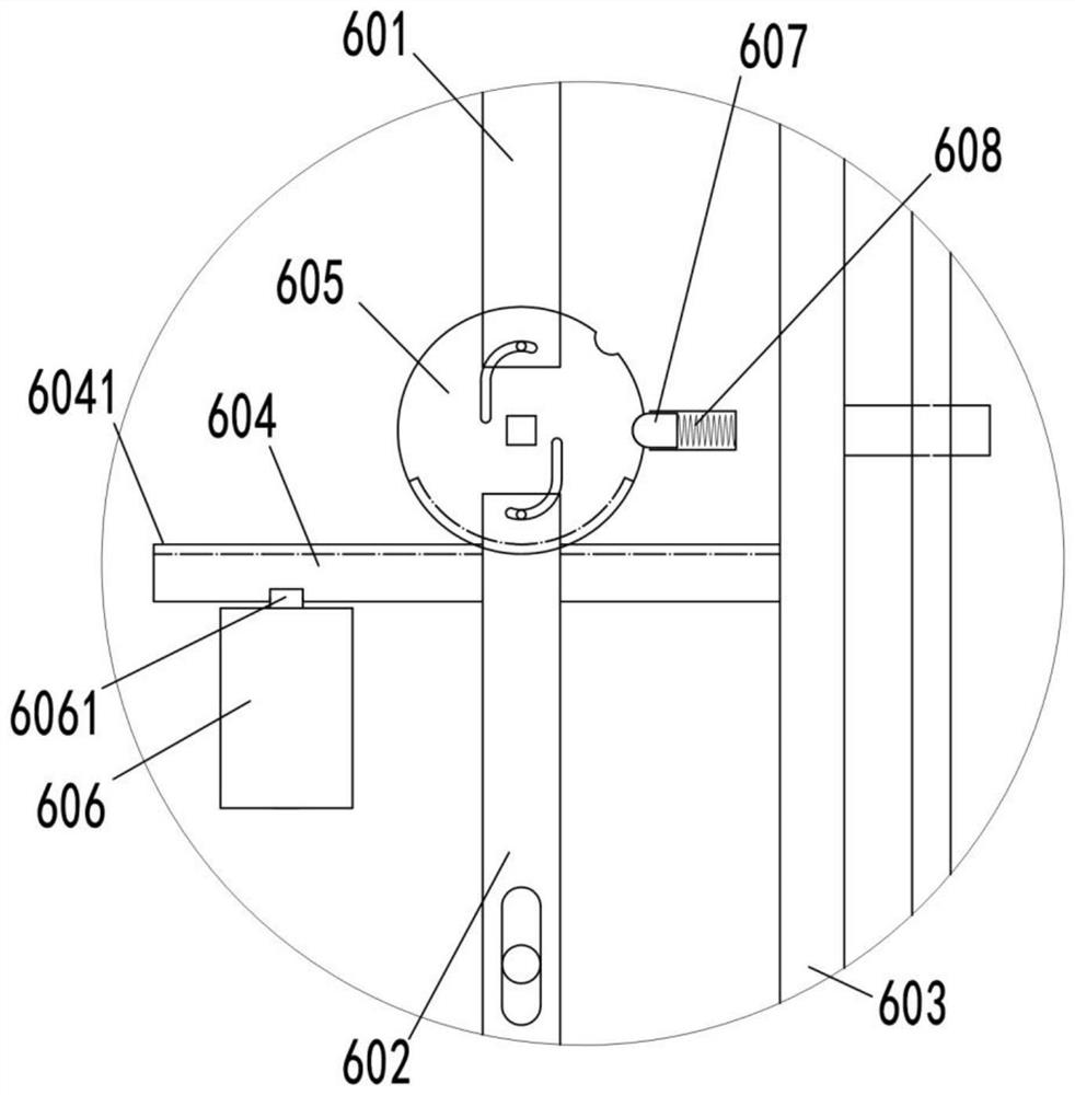
[0041] Such as Figure 1 to Figure 5 As shown, a bank intelligent trunk cabinet includes a cabinet body 1 , a cabinet door 2 and a locking device 6 . The cabinet body 1 is provided with a plurality of transverse partitions 5, and the partition boards 5 divide the inner space of the cabinet body 1 into a plurality of cavities for storing tail boxes.

[0042] Wherein, the cabinet door 2 is connected with the cabinet body 1 through a hinge 3 . The locking device 6 is arranged on the inner side of the cabinet door 2 and is used to realize the locking connection between the cabinet door 2 and the cabinet body 1 . The locking device 6 includes an upper locking bar 601 , a lower locking bar 602 , a side locking bar 603 , a cross bar 604 and a turntable 605 . The upper locking rod 601 and the lower locking rod 602 are respectively connected to the cabinet door 2 in a sliding ma...

no. 2 approach

[0050] This embodiment is further improved on the basis of the first embodiment, and an electric push rod 610 is added in this embodiment.

[0051] Such as Image 6 , Figure 7 with Figure 8 As shown, specifically, the lower surface of the cross bar 604 is provided with a locking groove and a tooth structure. The inner side of the cabinet door 2 is fixed with a sliding track 611 extending horizontally. The locking device 6 of this embodiment further includes an electric push rod 610 , a sliding seat 612 , a pushing rack 613 and a transmission gear 614 . The sliding seat 612 is connected with the sliding track 611, and the transmission gear 614 is rotatably connected with the cabinet door 2. The pushing rack 613 is fixedly connected with the sliding seat 612 . Push the rack 613 to mesh with the gear. The gear meshes with the toothed structure of the crossbar 604 . The telescopic rod portion of the electric push rod 610 is fixedly connected with the sliding seat 612 , an...

no. 3 approach

[0056] Such as Figure 9 , Figure 10 with Figure 11 As shown, this embodiment is further improved on the basis of the first embodiment, and the locking device 6 in this embodiment further includes an electric push rod 610 , a lever 615 and a support rod 616 . The lever 615 extends longitudinally. The support bar 616 can be horizontally slidably connected with the cabinet door 2, and the support bar is provided with at least two guide grooves 6162 extending in the horizontal direction, and the guide grooves 6162 are connected horizontally with the cabinet door by screws. The dual control lock 606 is disposed on the lower side of the support rod 616 , and the lock tongue 6061 of the dual control lock 606 is locked and connected with the locking groove 6161 on the support rod 616 . The left end of the support rod 616 is connected with the middle pin of the lever 615 . The electric push rod 610 is fixedly connected with the cabinet door 2 . The telescoping rod of electric p...


PUM


Abstract

A remote on-duty management system for a bank's intelligent tail box cabinet, which relates to the technical field of balance box storage equipment, including a bank intelligent tail box cabinet and a balance box control unit. The balance box control unit includes an identity verification module, an authority judgment module, a time judgment module, a communication module and the balance box detection module; the identity verification module is used to obtain the user's identity information and verify the user's identity; the authority judgment module is used to judge the user's operation authority; the time judgment module is used to judge whether the current time is business hours The communication module is used to communicate with the platform server, and the platform server is connected with a remote terminal; the balance box detection module is used to detect the status of the balance box, and the present invention can realize the safe storage and retrieval of the balance box.

Description

technical field [0001] The invention relates to the technical field of balance box storage equipment, in particular to a remote on-duty management system for bank intelligent tail box cabinets. Background technique [0002] The bank tail box refers to the metal cash box that is uniformly customized by the branches of various banks and used to store business cash, valuable documents, important blank vouchers and important accounting business seals. At present, bank tail boxes are usually picked up by escort companies every day, which requires professionals and professional equipment. The timeliness is uncontrollable, the safety is poor, and the cost of escort is also high. Contents of the invention [0003] Aiming at the above-mentioned technical problems existing in the prior art, the present invention provides a remote on-duty management system for a bank's intelligent tail box cabinet, which can realize the safe storage and retrieval of the balance box. [0004] In orde...

Claims


Application Information

Patent Timeline
Patent Type & Authority Patents(China)
IPC IPC(8): E05G1/10E05B65/52E05B3/00E05C9/06E05C9/12E05B47/00E05B45/06G07C9/00G06K7/10
CPCE05B3/00E05B45/06E05B47/0001E05B65/0075E05B2047/0056E05B2047/0067E05C9/063E05C9/12E05G1/10G06K7/10009G07C9/00309G07C9/00571G07C9/00912
Inventor 陈一兵段维新杨迪智
Owner 山东银保智能科技有限公司
Features
  • R&D
  • Intellectual Property
  • Life Sciences
  • Materials
  • Tech Scout
  • Unparalleled Data Quality
  • Higher Quality Content
  • 60% Fewer Hallucinations
Learn More