Wet cooling unit low-pressure cylinder zero-power heat supply system and work method

A heating system, low-pressure cylinder technology, applied in mechanical equipment, steam engine installations, machines/engines, etc., can solve problems such as high pipeline pressure, freezing damage to cooling towers, pipeline damage, etc., to increase heat load, reduce energy consumption, The effect of zero cold source loss

Pending Publication Date: 2020-07-31
SHANDONG HUADIAN ENERGY SAVING TECH
View PDF7 Cites 0 Cited by
  • Summary
  • Abstract
  • Description
  • Claims
  • Application Information

AI Technical Summary

Problems solved by technology

[0005] 1. Most of the steam is used for heating, resulting in less water entering the cooling tower at low temperature, resulting in freezing damage to the cooling tower
[0006] 2. A large amount of steam is used for heating, resulting in high pressure in the pipes that output steam from the high and medium pressure cylinders for heating, which may easily lead to damage to the pipes

Method used


Image

  • Wet cooling unit low-pressure cylinder zero-power heat supply system and work method

Examples


Embodiment 1

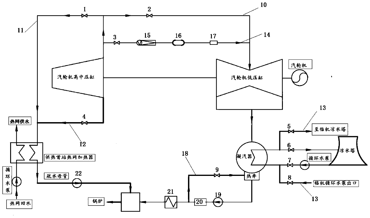
[0025] In the technical solutions disclosed in one or more embodiments, such as figure 1 As shown, a low-pressure cylinder zero-power heating system of a wet-cooling unit includes a steam turbine high-medium pressure cylinder, a steam turbine low-pressure cylinder, and a medium-low pressure communication pipe 10 connecting the steam turbine low-pressure cylinder intake end and the steam turbine high-medium pressure cylinder exhaust end, and the steam turbine low-pressure cylinder The steam exhaust end is connected to the cooling tower of this unit through the condenser, the sixth valve group 6, and the seventh valve group 7; a cooling bypass pipeline 13 can also be set, and the condenser is connected to the cooling tower through the cooling bypass pipeline 13 The cooling tower of another unit.

[0026] In this embodiment, cooling bypass pipes are arranged at the output end of the condenser to connect the cooling towers of other units except this unit, so that when the low-pres...

Embodiment 2

[0044] This embodiment provides a working method of the low-pressure cylinder zero-power heating system of the wet-cooling unit described in Embodiment 1, including the operation control method of the back pressure heating mode, the control method of the condensate heating operation mode and the control method of the pure condensate operation mode The method, the operation control method of the back pressure heating mode, includes the following steps:

[0045] Step 11, open the first valve group 1, the fourth valve group 4 and the drain pump 22;

[0046] Step 12, open the third valve group 3 of the desuperheating steam pipeline 14, the desuperheating and pressure reducing device 15, the steam-water separator 16 and the measuring module 17;

[0047] Step 13. Obtain the steam parameter data detected by the desuperheating steam pipeline 14. When the detected steam parameter data meets the steam conditions for zero-power operation of the low-pressure cylinder, switch the operating...


PUM


Abstract

The invention provides a wet cooling unit low-pressure cylinder zero-power heat supply system and a work method. The system comprises a steam turbine high and medium pressure cylinder, a steam turbinelow pressure cylinder and a medium and low pressure communication pipeline connecting a steam turbine low pressure cylinder gas inlet end and a steam turbine high and medium pressure cylinder steam exhaust end, the steam exhaust end of the steam turbine low pressure cylinder is connected to a cold water tower of a unit through a condenser, a sixth valve group and a seventh valve group, a coolingbypass pipeline is mounted, the condenser is connected to a cold water tower of the other unit through a cooling bypass pipeline, through the cold water towers of the adjacent units, cooling is carried out, the cold water tower in the unit and a circular water pump connected with the cold water tower are in the non-work state, the icing damage of the cold water tower caused by the fact that waterwith the small flow enters the cold water tower can be avoided, meanwhile, the start number of the circular water pump and the cold water tower of the whole unit can be reduced, and the energy consumption is greatly reduced.

Description

technical field [0001] The present disclosure relates to the related technical field of heat and power cogeneration system, and specifically relates to a low-pressure cylinder zero-power heating system and working method of a wet-cooling unit. Background technique [0002] The statements in this section merely provide background information related to the present disclosure and may not necessarily constitute prior art. [0003] In recent years, in order to improve the utilization rate of clean energy, the country has to compress the traditional thermal power load to make way for the use of clean energy, reduce the power generation load of thermal power units, and ensure the grid connection of clean energy. However, there are some heat and power cogeneration central heating units in northern thermal power units. When the units are running, they operate in a heat-fixed power mode, that is, the electric load and the heat load are interrelated. The increase or decrease of the el...

Claims


Application Information

Patent Timeline
IPC IPC(8): F01K11/02F01K13/02F01K17/02
CPCF01K11/02F01K13/006F01K17/02F01K13/02
Inventor 洪涛岳建楠周国峰王爱民刘建华李超靳芳李媛邹萌
Owner SHANDONG HUADIAN ENERGY SAVING TECH
Why Eureka
Try Eureka