High stability control valve with valve stem protection structure and working method

A technology with protective structure and high stability, which is applied in the field of regulating valves, can solve the problems of increasing the difficulty of regulating valves, reducing the stability of regulating valves, and the inability to perform double locking operations, so as to avoid accidental opening and improve stability.

Active Publication Date: 2022-01-04
CAMBRIDGE VALVE IND GRP CO LTD
View PDF8 Cites 0 Cited by
  • Summary
  • Abstract
  • Description
  • Claims
  • Application Information

AI Technical Summary

Problems solved by technology

[0005] In order to overcome the fact that the traditional high-stability control valve does not have an auxiliary locking structure, the traditional control valve is manually driven and operated, which makes the control valve prone to loosening under the influence of external forces, thereby reducing the safety of the control valve when it is used, and it cannot be repaired. Double locking operation; Secondly, the traditional high-stability control valve adopts an integrated structure design. When the sealing of the high-stability control valve has problems, the user needs to disassemble and maintain the entire control valve, thereby increasing the disassembly and maintenance of the control valve. Difficulty in operation, secondly, the traditional high-stability control valve does not have a stem protection structure, which reduces the stability of the control valve during use, and provides a high-stability control valve with a stem protection structure

Method used


Image

  • High stability control valve with valve stem protection structure and working method
  • High stability control valve with valve stem protection structure and working method
  • High stability control valve with valve stem protection structure and working method

Examples


Embodiment Construction

[0033] The technical solutions in the embodiments of the present invention will be clearly and completely described below in conjunction with the embodiments of the present invention. Apparently, the described embodiments are only some of the embodiments of the present invention, not all of them. Based on the embodiments of the present invention, all other embodiments obtained by persons of ordinary skill in the art without creative efforts fall within the protection scope of the present invention.

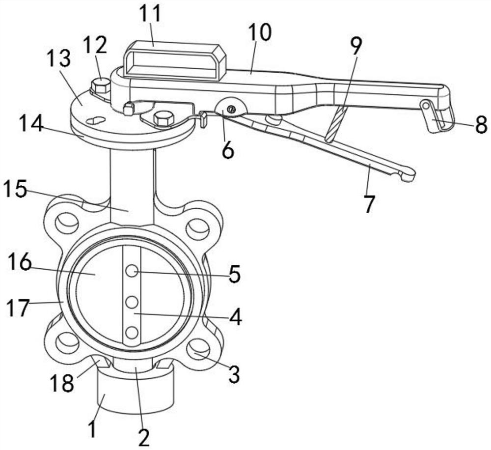
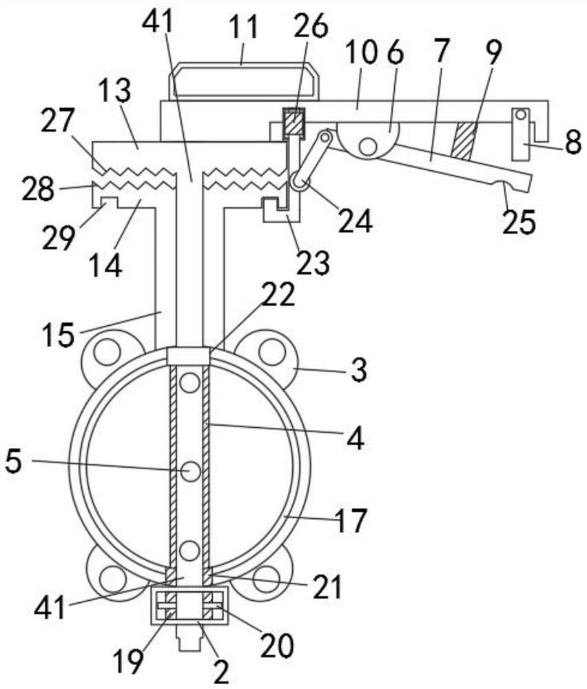
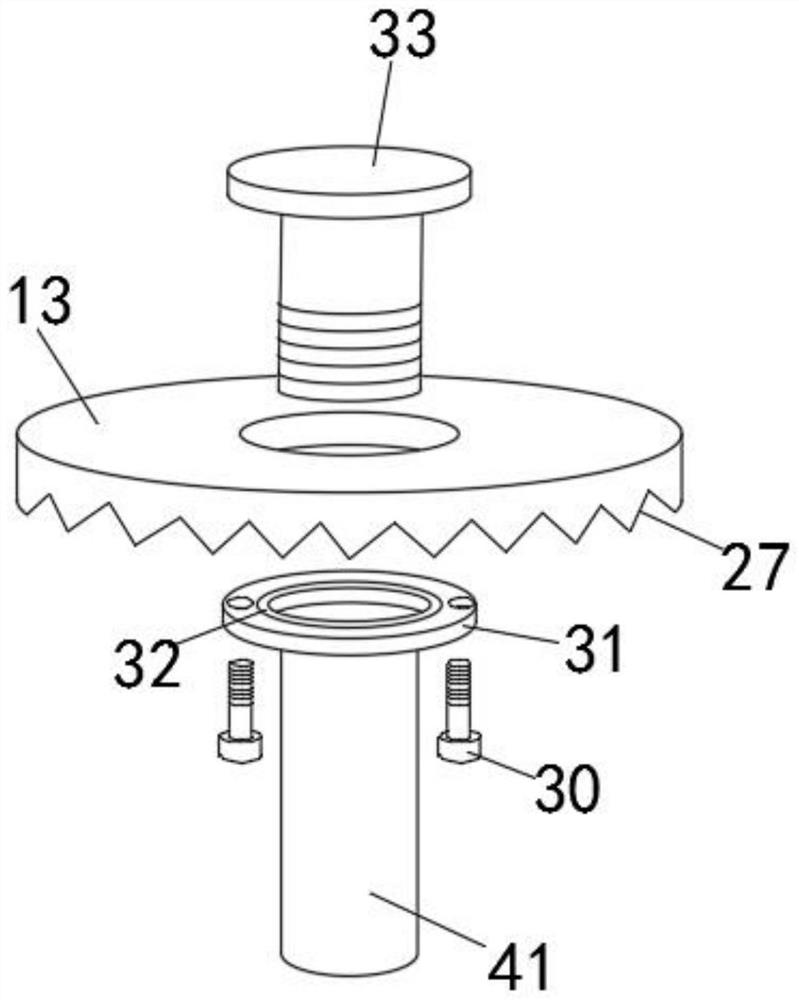
[0034] like Figure 1-6 As shown, the high-stability regulating valve with a valve stem protection structure includes a first chuck 13, a second chuck 14, a docking valve body 17 and a rotating valve stem 4, and the rotating valve stem 4 is movably installed on the butt joint valve body 17. In the middle position of the inner side, splicing valve plates 16 are fixedly installed on both sides of the rotating valve stem 4, and the inner inner surface of the rotating valve stem 4 is ...


PUM


Abstract

The invention discloses a high-stability regulating valve with a valve rod protection structure, which includes a first chuck, a second chuck, a docking valve body and a rotating valve rod, and the rotating valve rod is movably installed in the middle of the inner side of the docking valve body position, the outer surface of both sides of the rotating valve stem is fixedly installed with a splicing valve plate, the inner inner surface of the rotating valve stem is movably socketed with an inner sleeve rod, and the side outer surface of the splicing valve plate is fixedly installed There is a combined clamping plate, and the inner surface of both sides of the rotating valve stem is provided with a splicing clamping groove, and the rotating valve stem and the splicing valve plate are fixed by butt jointing the splicing clamping groove and the combined clamping plate; the present invention has valve stem protection The structure of the high-stability control valve makes the control valve have a stem protection structure, which improves its stability during use and prevents the valve stem from loosening. At the same time, it has a splicing combined fixed structure, which makes its installation and disassembly operations more convenient.

Description

technical field [0001] The technical field of the regulating valve of the present invention is, in particular, a highly stable regulating valve with a valve stem protection structure. Background technique [0002] Valves are the control components in the fluid delivery system. They have the functions of cut-off, adjustment, flow diversion, reverse flow prevention, pressure stabilization, flow diversion or overflow pressure relief. Valves used in fluid control systems range from the simplest cut-off valve to extremely complex There are various types and specifications of valves used in the automatic control system. [0003] Patent document CN104976418B discloses a throttling part of a flow regulating valve, which includes a cylindrical throttling body. The outer wall of the throttling body is provided with a spiral groove for reducing the fluid velocity. One end surface of the throttling body is A fluid inlet is provided for fluid to enter the spiral groove, and a fluid outl...

Claims


Application Information

Patent Timeline
Patent Type & Authority Patents(China)
IPC IPC(8): F16K1/226F16K1/36F16K1/32F16K31/05F16K31/60F16K31/53F16K27/02F16K35/00
CPCF16K1/2261F16K1/2268F16K1/36F16K1/32F16K31/05F16K31/60F16K31/53F16K27/0218F16K35/00
Inventor 王加齐王小雷
Owner CAMBRIDGE VALVE IND GRP CO LTD
Why Eureka
Try Eureka