Device and method for measuring wing falling, rocking and washing time difference of aircraft

A technology of aircraft and jet lag, applied in the field of wind tunnel experiments, can solve problems such as wing loss, large mass and inertia of translation mechanism, and reduced lift force, and achieve the effects of reducing wind tunnel blockage, high stiffness, high position and attitude control accuracy

Active Publication Date: 2020-07-31
RIZHAO KUNLUN INTELLIGENT TECH CO LTD
View PDF11 Cites 5 Cited by
  • Summary
  • Abstract
  • Description
  • Claims
  • Application Information

AI Technical Summary

Problems solved by technology

[0005] CN106840583A discloses a subtransonic wind tunnel large angle of attack mechanism with translation function, and CN106840584A discloses a multi-degree-of-freedom subtransonic wind tunnel large angle of attack mechanism. Although the translation range of the mechanism is relatively large, the translation mechanism The mass and inertia are very large, it is difficult to meet the requirements of large translational velocity and acceleration, and it can only provide a vertical movement
When the left and right wings of the aircraft, especially the wingtips, appear asymmetrical stall, the lift force of the stalled part is greatly reduced, forming a wing-drop phenomenon in which the entire wing falls rapidly, and also causes the longitudinal axis of the fuselage to swing up and down, left and right, causing The maneuverability and agility of the aircraft are greatly restricted
So far, it has not been possible to obtain the aerodynamic phenomenon and mechanism of the up and down, left and right swings of the longitudinal axis of the fuselage during the actual process of wing loss.

Method used


Image

  • Device and method for measuring wing falling, rocking and washing time difference of aircraft
  • Device and method for measuring wing falling, rocking and washing time difference of aircraft
  • Device and method for measuring wing falling, rocking and washing time difference of aircraft

Examples


Embodiment Construction

[0045] In order to clearly illustrate the technical characteristics of this solution, the specific implementation of the present invention will be further described below according to the accompanying drawings.

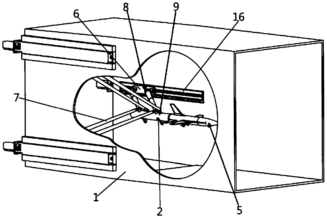
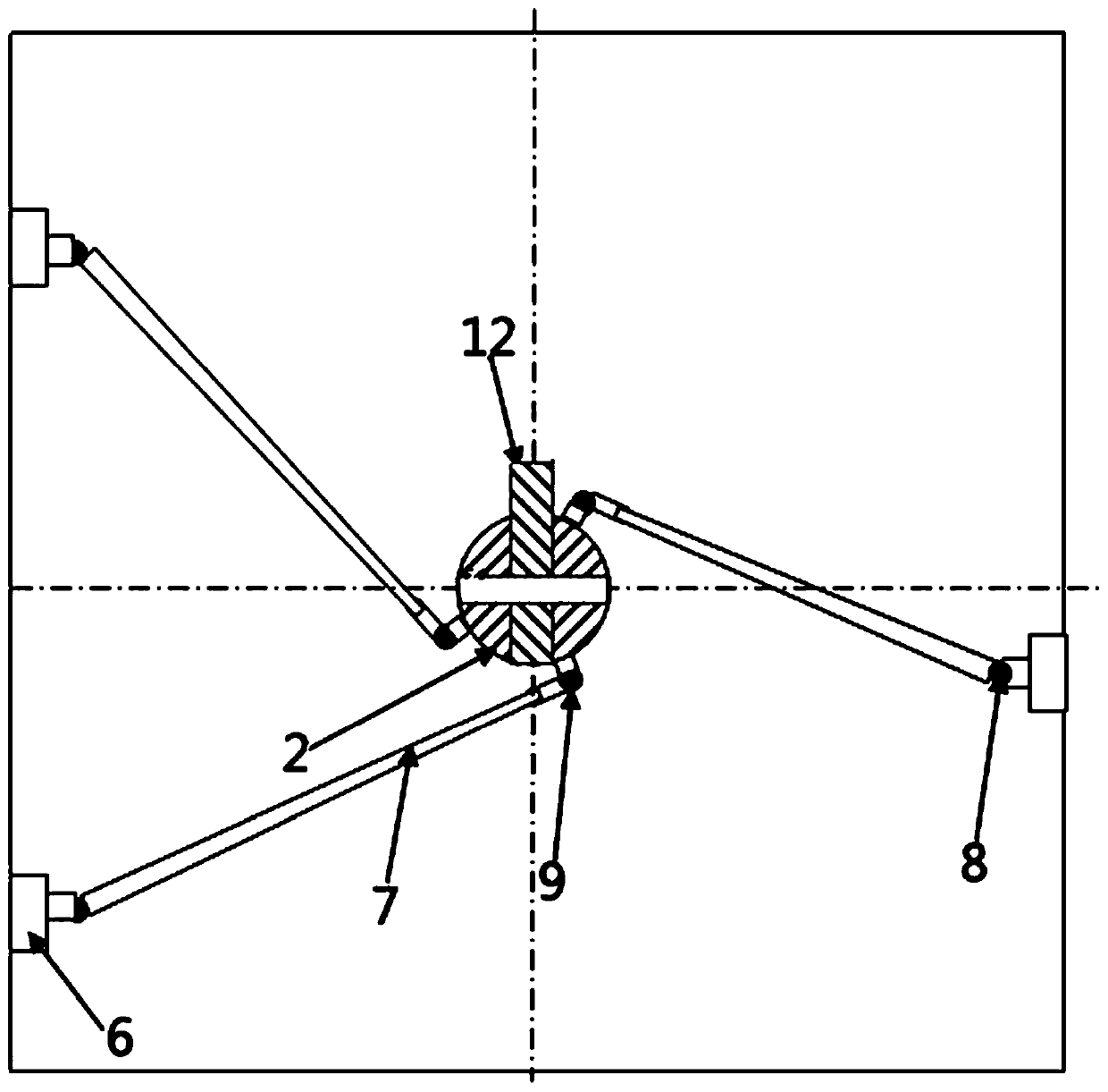
[0046] Such as Figure 1-Figure 5 As shown, a device for measuring wing drop, roll and washout time difference of an aircraft includes a wind tunnel 1, a parallel linkage mechanism, a tail strut 2, a variable pitch angle device, a multi-component balance 4, a roll drive device, and an aircraft model 5. Roll angle measuring device and pitch angle measuring device.

[0047] The parallel link mechanism is provided with three groups, and the parallel link mechanism includes a linear drive device, a slide block 6 and parallel bar groups. The linear drive device is installed in the wind tunnel 1. The linear drive device of this embodiment is a linear module 16, which can drive the slider 6 to move in a direction parallel to the axis of the wind tunnel 1. Three groups of li...


PUM


Abstract

The invention belongs to the technical field of wind tunnel experiments, and particularly relates to a device for measuring wing falling, rocking and washing time difference of an aircraft, which comprises a wind tunnel, parallel rod mechanisms, a tail support rod, a variable pitch angle device, a multi-component balance, a rolling driving device and an aircraft model, wherein the three sets of parallel rod mechanisms are arranged, and each parallel rod mechanism comprises a linear driving device, a sliding block and a parallel rod set; and the parallel rod set comprises two connecting rods arranged in parallel. The aircraft model can move in the wind tunnel at a large scale and a high speed, the mechanism rigidity is high, and the wind tunnel blockage degree is small; in addition, the initial pitch angle of the aircraft model can be changed as required by changing the pre-deflection angle of the multi-component balance, so that the rocking or wing falling phenomenon of the model wingis measured; in addition, the body axis of the aircraft model can also move in parallel according to the aerodynamic force measured inside the model when the wings rock or fall off.

Description

technical field [0001] The invention belongs to the technical field of wind tunnel experiments, and in particular relates to a device and method for measuring aircraft wing drop, roll and washout time difference. Background technique [0002] Modern military aircraft require greater maneuverability and agility. The traditional method of changing the altitude or track by maneuvering at a large angle has been difficult to fully meet the requirements of actual combat. By directly changing the altitude or trajectory (such as the thrust vectoring method), it is faster, takes less time, and has higher agility than traditional high-angle-of-attack maneuvers. However, the non-linear and unsteady aerodynamic characteristics (such as jet lag, wing drop and wing roll, etc.) caused by directly changing the altitude or flight path must be understood. [0003] For jet lag, when the aircraft is pitching and maneuvering, the instantaneous geometric angle of attack and the local ground was...

Claims


Application Information

Patent Timeline
IPC IPC(8): G01M9/08G01M9/04G01M9/06B64F5/60
CPCG01M9/08G01M9/04G01M9/067B64F5/60
Inventor 黄兴中宋法振田素营
Owner RIZHAO KUNLUN INTELLIGENT TECH CO LTD
Why Eureka
Try Eureka