Hinged Array Ultrasonic Phased Array Transducer Probe Control Method

An ultrasonic phased array and control method technology, applied in the analysis of solids using sonic/ultrasonic/infrasonic waves, material analysis using sonic/ultrasonic/infrasonic waves, instruments, etc. , to reduce the detection error

Active Publication Date: 2021-06-01
HARBIN INST OF TECH
View PDF7 Cites 0 Cited by
  • Summary
  • Abstract
  • Description
  • Claims
  • Application Information

AI Technical Summary

Problems solved by technology

The problems of this method are: the electromagnetic conversion efficiency is low, the sensitivity depends on the gap between the probe and the flaw detection object, and special fixtures are required for detection
The problem with this method is that it is impossible to ensure that the pressure values ​​of the piezoelectric array elements of the transducer are consistent before detection, resulting in detection errors and limited application range.
[0006] At present, the detection methods based on ultrasonic phased array transducers on the market are roughly divided into two categories. One is the ultrasonic detection method based on planar ultrasonic phased array transducers. However, such methods cannot be applied to curved surfaces. The detection of the test piece; the other is the ultrasonic detection method based on the roller ultrasonic phased array transducer. Although this type of method can take into account the surface of the test piece with a flat or curved surface, it is difficult to ensure that the ultrasonic The pressure value of each piezoelectric array element of the phased array transducer is the same, which causes detection errors and affects the detection results
To sum up, the current market lacks an ultrasonic phased array transducer and its control method that takes into account the testing surface of a test piece with a flat or curved surface.

Method used


Image

  • Hinged Array Ultrasonic Phased Array Transducer Probe Control Method
  • Hinged Array Ultrasonic Phased Array Transducer Probe Control Method
  • Hinged Array Ultrasonic Phased Array Transducer Probe Control Method

Examples


Embodiment Construction

[0016] Below in conjunction with accompanying drawing, the present invention is described in further detail:

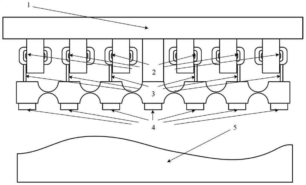
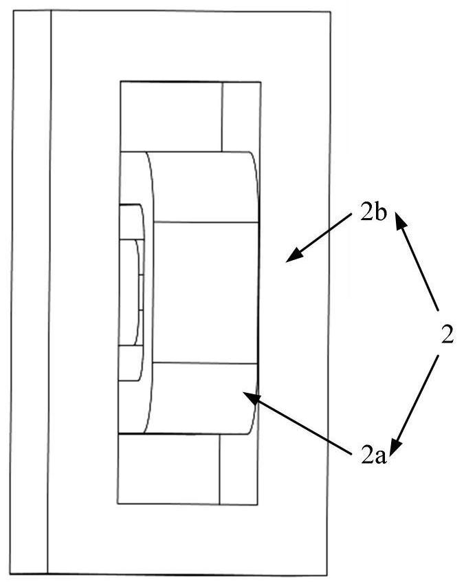
[0017] A hinge array ultrasonic phased array transducer probe control method, the method is: firstly fix the test piece 5, make the central piezoelectric array element of the piezoelectric array element 4 contact with the surface of the test piece 5, and then Fix the fixed bracket 1; the magnetic cylinder 2b of the voice coil motor is symmetrically arranged and fixedly connected to the fixed bracket 1; before starting the test, use the voice coil motor 2 to drive the hinge array so that the piezoelectric array element 4 is completely attached to the surface of the DUT 5 The number of piezoelectric array elements is 2N+1 (N=1, 2, 3, 4, 5), and different N values ​​are selected according to the size of the test piece; the piezoelectric array element 4 As a pressure sensor, collect each pressure value, F 1 , F 2 ,...,F N ,...,F 2N , F 2N+1 ; Take the pressure value ...


PUM


Abstract

A hinge array ultrasonic phased array transducer probe control method belongs to the field of ultrasonic detection technology. The control method firstly fixes the object to be tested so that the central piezoelectric array element of the hinge array ultrasonic phased array transducer The surface of the test piece is in contact, and then the fixed bracket is fixed; before starting the test, the hinge array is driven by a voice coil motor to make each piezoelectric array element fit the surface of the test piece completely, and the number of piezoelectric array elements is 2N+ 1 (N=1, 2, 3, 4, 5), select different N values ​​according to the size of the test piece; take the pressure value of the central piezoelectric array element as the standard, and the difference between the pressure values ​​of the other piezoelectric array elements and Values ​​are used as the control signals corresponding to the voice coil motor coils to control the output rod to drive the hinge array; the incremental digital PID control method is used to keep the pressure values ​​of each piezoelectric array element consistent; after that, the ultrasonic deflection and Focus on ultrasonic testing to realize the detection of the surface of the test piece with a flat or curved surface.

Description

technical field [0001] The invention belongs to the technical field of ultrasonic detection, and mainly relates to a method for controlling a hinge array ultrasonic phased array transducer probe. Background technique [0002] In recent years, with the rapid development of the industrial level, aerospace and weaponry have higher and higher requirements for key structures and performances. The processing and working environment are very easy to cause defects such as holes, cracks and inclusions in the product structure. Defects cannot be detected in time and accurately, which can easily lead to various accidents. Ultrasonic testing technology is characterized by its good directivity, high penetrating power, high sensitivity, high efficiency, high energy, wide detection range, large detection depth, accurate positioning; intuitive and easy to automate; low cost, simple operation, safe and The advantages of easy application have been widely used in the detection field. [0003...

Claims


Application Information

Patent Timeline
Patent Type & Authority Patents(China)
IPC IPC(8): G01N29/22
CPCG01N29/221G01N29/04G01N29/223G01N29/2437G01N29/262G01N2291/106G01N2291/2638G01N29/225
Inventor 史维佳王丙泉赵勃谭久彬
Owner HARBIN INST OF TECH
Why Eureka
Try Eureka