Laser ranging method and device and self-moving equipment

A technology of laser ranging and receiving devices, which is applied in measuring devices, measuring distances, line-of-sight measurement, etc., can solve the problems of complex calculation, ranging accuracy easily interfered by light, etc., and high cost, and achieve the effect of improving detection accuracy

Pending Publication Date: 2020-07-31
ECOVACS ROBOTICS (SUZHOU ) CO LTD
View PDF7 Cites 2 Cited by
  • Summary
  • Abstract
  • Description
  • Claims
  • Application Information

AI Technical Summary

Problems solved by technology

The binocular imaging device calculates the pixel difference of the same feature on the image of the left and right imaging devices, the calculation is complex, the cost is high, and the distance measurement accuracy is easily disturbed

Method used


Image

  • Laser ranging method and device and self-moving equipment
  • Laser ranging method and device and self-moving equipment
  • Laser ranging method and device and self-moving equipment

Examples


Embodiment Construction

[0047] In the following description, numerous specific details are set forth in order to provide a thorough understanding of the application. However, the present application can be implemented in many other ways different from those described here, and those skilled in the art can make similar promotions without violating the connotation of the present application. Therefore, the present application is not limited by the specific implementation disclosed below.

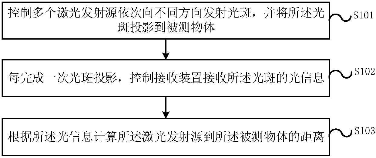
[0048] An embodiment of the present application provides a laser ranging method, figure 1 It is a schematic flow chart of the laser ranging method provided in the embodiment of the present application, such as figure 1 As shown, the process of the laser ranging method in the embodiment of the present application includes the following steps:

[0049] Step S101, controlling a plurality of laser emitting sources to emit light spots in different directions sequentially, and project the light spots onto the measured obj...


PUM


Abstract

The invention discloses a laser ranging method, which comprises the steps of controlling a plurality of laser emission sources to emit light spots to different directions in sequence, and projecting the light spots to a measured object; controlling a receiving device to receive the light information of the light spot every time the light spot projection is completed; and calculating the distance from the laser emission source to the measured object according to the light information. Light spots are emitted to different directions through the emission source, so that multi-angle detection of afront obstacle is realized, the light information of the light spots projected at each angle is processed and calculated, the detection precision is improved while the distance from the laser emission source to a measured object is obtained, and the obstacle can be effectively avoided.

Description

technical field [0001] The present application relates to the field of laser ranging, in particular to a laser ranging method, a laser ranging device, and a self-moving device. Background technique [0002] With the development of science and technology, there are more and more intelligent machines that can walk automatically. Among them, in the process of intelligent machine walking, obstacle avoidance is a crucial issue. The currently used obstacle avoidance method is mainly to directly or indirectly know the relative distance between the obstacle and the machine through the collision ring sensor, ultrasonic sensor, infrared sensor, infrared scanning sensor or visual sensor, so as to realize obstacle avoidance. [0003] However, the collision sensor is in contact with the obstacle through the collision ring, so as to judge the approximate orientation of the obstacle. Since the obstacle avoidance can only be realized through the collision, the user experience is relatively...

Claims


Application Information

Patent Timeline
IPC IPC(8): G01S17/48G01S7/481
CPCG01S17/48G01S7/4815
Inventor 汤进举
Owner ECOVACS ROBOTICS (SUZHOU ) CO LTD
Why Eureka
Try Eureka