Internal focusing type imaging lens
An imaging lens, internal focus technology, applied in optical components, optics, instruments, etc., to achieve the effect of reducing weight, improving edge spherical aberration, and suppressing total length
- Summary
- Abstract
- Description
- Claims
- Application Information
AI Technical Summary
Problems solved by technology
Method used
Image
Examples
Embodiment 1
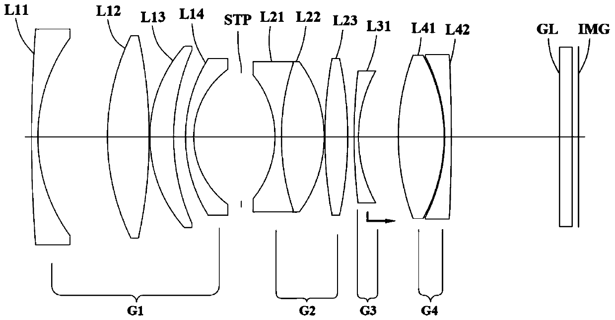
[0077] figure 1 Shown is the structural schematic diagram of the imaging lens of Embodiment 1, and the numerical data of the imaging lens are shown in Table 1 and Table 2:
[0078] Table 1
[0079]
[0080]
[0081] Table 2
[0082]
[0083] Wherein, the surface number represents the surface number of each lens from the object side to the image side;
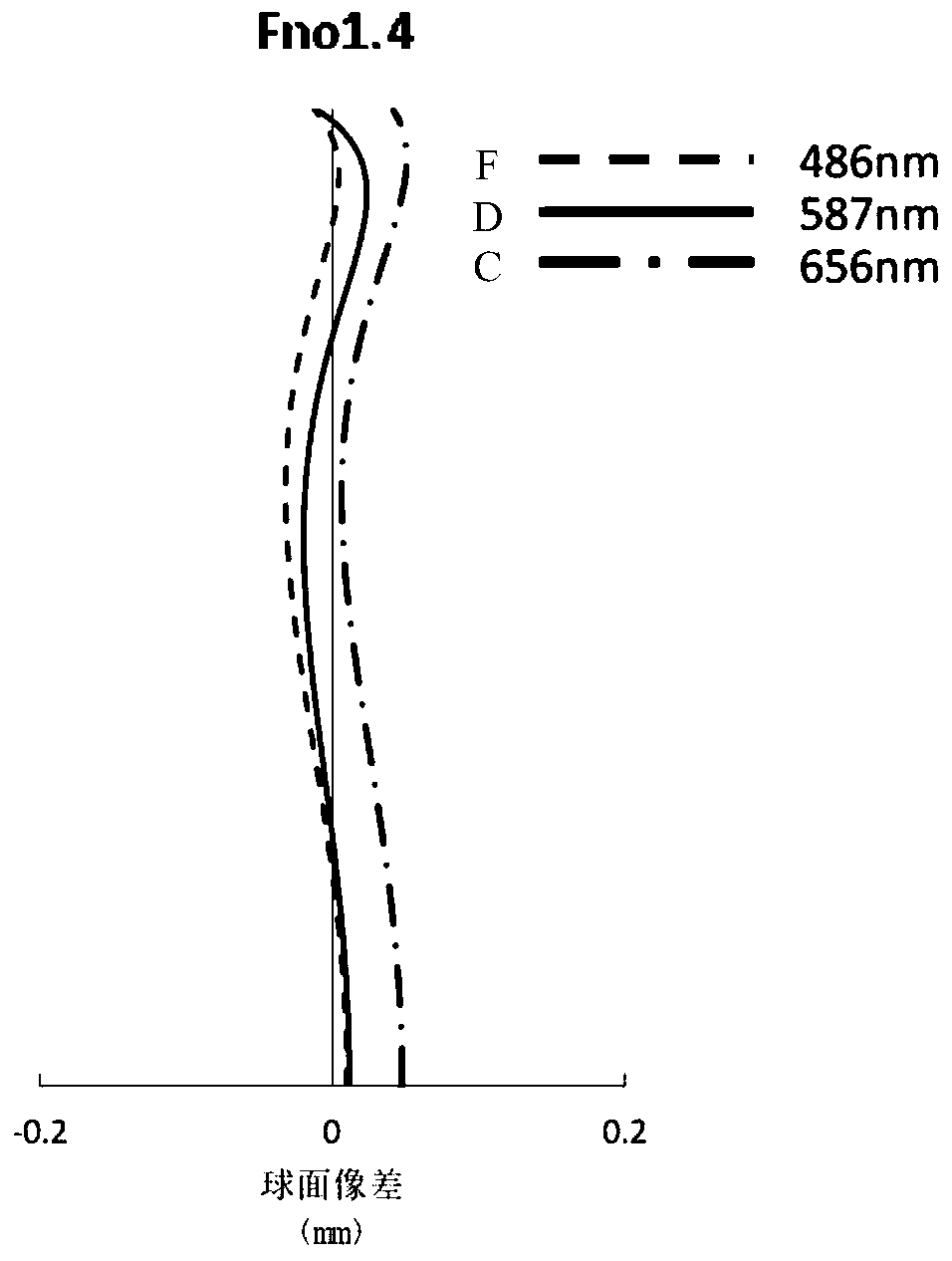
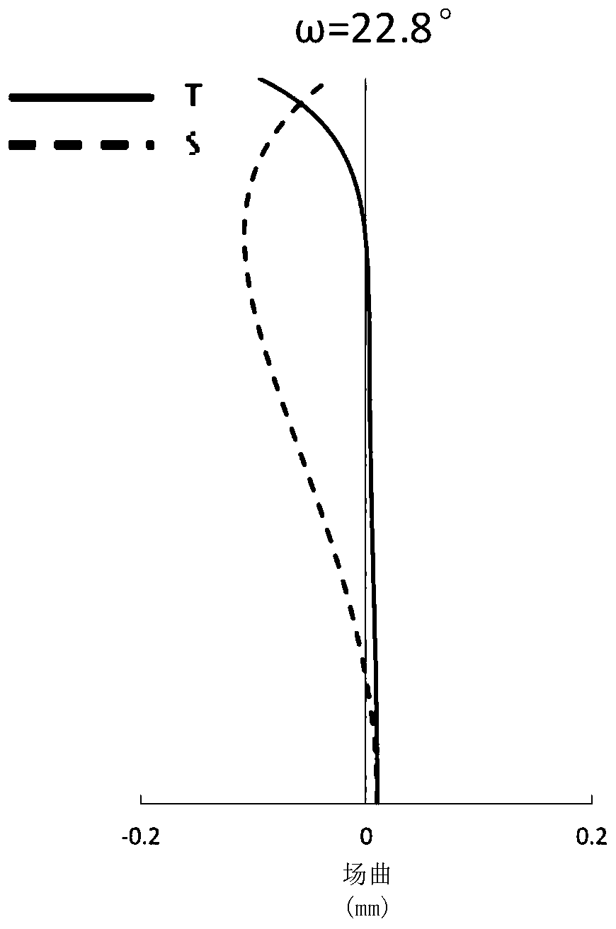
[0084] Figure 2-4 Showing the spherical aberration, curvature of field, and distortion curves of embodiment 1 at infinity focus, Figure 5-7 The spherical aberration, curvature of field, and distortion curves of Example 1 at the shortest focusing distance are shown.
[0085] The spherical aberration curve graph shows the spherical aberration curve when the aperture number is 1.4, among which, the F line, D line, and C line represent the spherical aberration at the wavelength of 486nm, the wavelength of 587nm, and the wavelength of 656nm respectively, and the abscissa indicates the spherical aberration The magnitud...
Embodiment 2
[0087] Such as Figure 8 As shown, the difference between this embodiment and Embodiment 1 lies in that the lens parameters of the imaging lens are different. Hereinafter, Table 3 and Table 4 show various numerical data about the imaging lens of this embodiment.
[0088] table 3
[0089]
[0090]
[0091] Table 4
[0092]
[0093] Figure 9-11 Showing the spherical aberration, curvature of field, and distortion curves of Example 2 at infinity focus, Figure 12-14 The spherical aberration, curvature of field, and distortion curves of Example 2 at the shortest distance are shown. It can be seen from Figures 9-14 that the imaging lens of this embodiment has a good imaging effect.
Embodiment 3
[0095] Such as Figure 15 As shown, the difference between this embodiment and Embodiment 1 lies in that the lens parameters of the imaging lens are different. Hereinafter, Table 5 and Table 6 show various numerical data about the imaging lens of this embodiment.
[0096] table 5
[0097]
[0098]
[0099] Table 6
[0100]
[0101] Figure 16-18 Showing the spherical aberration, curvature of field, and distortion curves of Example 3 at infinity focus, Figure 19-21 The spherical aberration, curvature of field, and distortion curves of Example 3 at the shortest focusing distance are shown. It can be seen from Figures 16-21 that the imaging lens of this embodiment has a good imaging effect.
PUM
 Abstract
Description
Claims
Application Information
 - R&D
- Intellectual Property
- Life Sciences
- Materials
- Tech Scout
- Unparalleled Data Quality
- Higher Quality Content
- 60% Fewer Hallucinations
Browse by: Latest US Patents, China's latest patents, Technical Efficacy Thesaurus, Application Domain, Technology Topic, Popular Technical Reports.
© 2025 PatSnap. All rights reserved.Legal|Privacy policy|Modern Slavery Act Transparency Statement|Sitemap|About US| Contact US: help@patsnap.com


