

JBOD interface testing device and method
An interface testing and interface technology, which is applied in the server field to achieve the effect of expanding the scope of application, widening application prospects and ensuring product quality
- Summary
- Abstract
- Description
- Claims
- Application Information
AI Technical Summary
Problems solved by technology
Method used
Image

Examples
Embodiment 1
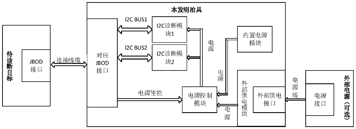
[0033] Please refer to figure 1 , the present embodiment provides a JBOD interface testing device, the device comprising:
[0034] A read-write diagnostic module (I2C diagnostic module 1 and I2C diagnostic module 2), a power control module and a power supply, the read-write diagnostic module is connected to the target JBOD interface through the I2C bus, the read-write diagnostic module is connected to the power control module, and the power supply The control module is connected to the power supply, and the power supply control module is connected to the target JBOD interface. Among them, the read-write diagnostic module and the power control module are mounted on the chip supporting I2C.
Embodiment 2
[0036] Such as figure 1 As shown, the present embodiment provides a JBOD interface testing device, comprising:
[0037] A read-write diagnostic module (I2C diagnostic module 1 and I2C diagnostic module 2), a power control module and a power supply, the read-write diagnostic module is connected to the target JBOD interface through the I2C bus, the read-write diagnostic module is connected to the power control module, and the power supply The control module is connected to the power supply, and the power supply control module is connected to the target JBOD interface. The read-write diagnostic module is mounted on the control chip, and the power control module uses FPGA.
[0038] Among them, the read-write diagnostic module (I2C diagnostic module 1, I2C diagnostic module 2): this module is used to realize data interaction with the JBOD port of the "target to be diagnosed" through the I2C protocol, and is realized as the main body of the fixture function of the present invention...
Embodiment 3
[0042] The present embodiment provides a kind of JBOD interface testing method, comprises the steps:
[0043] S1. The power control module verifies that the target JBOD interface is in place by receiving the ground signal of the target JBOD interface.
[0044] The power control module judges whether the ground signal of the target JBOD interface is received. If it is received, it determines that the target JBOD interface is in place, and sends the in-position signal to the read-write diagnostic module to trigger the read-write diagnostic module to start diagnosis. If the target JBOD interface is not received ground signal, it means that the target JBOD interface does not exist, and an error message is output.
[0045] S2. The read-write diagnostic module sends a read-write command to the target JBOD interface, and obtains a read-write execution result according to information returned by the target JBOD interface.
[0046] After using the network cable to connect the JBOD int...
PUM
 Abstract
Description
Claims
Application Information