Unmanned aerial vehicle aerial image defogging processing method and system based on image matching
A processing method and a technology of a processing system, which are applied in the field of UAV aerial image defogging processing, can solve problems such as the degradation of UAV aerial image quality, achieve good processing effects, and maintain the effect of original image information
- Summary
- Abstract
- Description
- Claims
- Application Information
AI Technical Summary
Problems solved by technology
Method used
Image
Examples
Embodiment 1
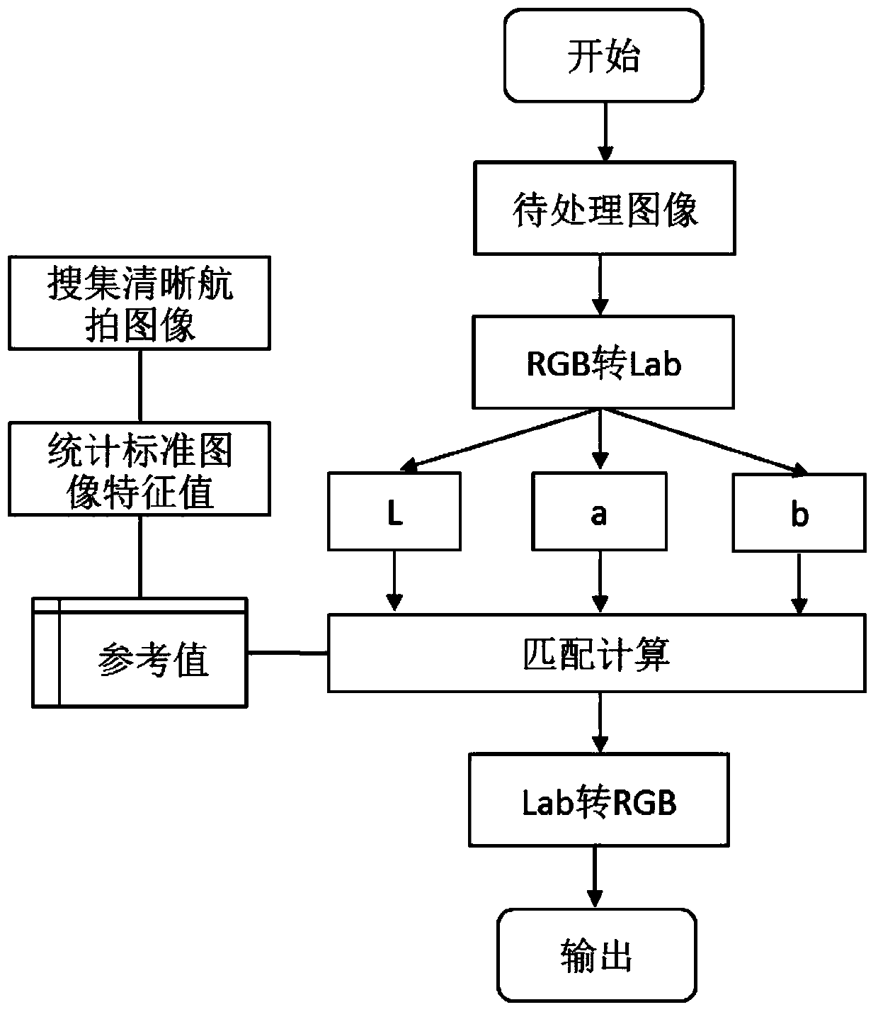
[0034] Aiming at the problem of poor aerial image quality caused by the foggy environment, this embodiment provides a clearing processing method based on image matching. This method mainly includes the following steps:
[0035] Convert the input target image to be processed from the RGB color space to the LAB color space to obtain the LAB image;
[0036] Since the LAB color model is based on the human perception of color, and its numerical values describe all the colors that humans can see, LAB describes how colors are displayed, not what is needed for a device (such as a monitor, desktop printer, or digital camera) to generate colors The value of a specific color, so LAB is regarded as a device-independent color model, and the LAB color space has the advantages of a wider color gamut. Therefore, by converting the originally collected foggy image, that is, the target image to be processed, into the RGB color space Converted to LAB color space, in LAB mode, the foggy part can...
Embodiment 2
[0052] refer to image 3 As shown, the present embodiment provides an image matching-based UAV aerial image defogging processing system, including:
[0053] The conversion module 31 is configured to convert the input target image to be processed from the RGB color space to the LAB color space.
[0054] Since the LAB color model is based on the human perception of color, and its numerical values describe all the colors that humans can see, LAB describes how colors are displayed, not what is needed for a device (such as a monitor, desktop printer, or digital camera) to generate colors The value of a specific color, so LAB is regarded as a device-independent color model, and the LAB color space has the advantages of a wider color gamut. Therefore, by converting the originally collected foggy image, that is, the target image to be processed, into the RGB color space Converted to LAB color space, in LAB mode, the foggy part can be better distinguished.
[0055] The matching ope...
Embodiment 3
[0071] refer to Figure 5 As shown, the image matching-based UAV aerial image defogging processing device provided in this embodiment includes a processor 51, a memory 52, and a computer program 53 stored in the memory 52 and operable on the processor 51, For example, the image matching based UAV aerial image defogging program. When the processor 51 executes the computer program 53, the steps of the above-mentioned embodiment 1 are realized, for example figure 1 steps shown. Alternatively, when the processor 51 executes the computer program 53, the functions of the modules / units in the second embodiment above are realized.
[0072] Exemplarily, the computer program 53 can be divided into one or more modules / units, and the one or more modules / units are stored in the memory 52 and executed by the processor 51 to complete this invention. The one or more modules / units may be a series of computer program instruction segments capable of completing specific functions, and the ins...
PUM
 Abstract
Description
Claims
Application Information
 - R&D
- Intellectual Property
- Life Sciences
- Materials
- Tech Scout
- Unparalleled Data Quality
- Higher Quality Content
- 60% Fewer Hallucinations
Browse by: Latest US Patents, China's latest patents, Technical Efficacy Thesaurus, Application Domain, Technology Topic, Popular Technical Reports.
© 2025 PatSnap. All rights reserved.Legal|Privacy policy|Modern Slavery Act Transparency Statement|Sitemap|About US| Contact US: help@patsnap.com


