Short-circuit protection device

A technology of short-circuit protection and protection cavity, which is applied to the power devices, circuits, electrical components and other directions inside the switch, can solve the problems of inconvenience and manual opening, and achieve the advantages of increasing safety, increasing the safety of electricity consumption, and automatic recovery of short-circuit protection. Effect

Active Publication Date: 2020-07-31
深圳市中创电测技术有限公司
View PDF3 Cites 2 Cited by
  • Summary
  • Abstract
  • Description
  • Claims
  • Application Information

AI Technical Summary

Problems solved by technology

[0004] The purpose of the present invention is to solve the disadvantages in the prior art that need to be manually opened after the short-circuit protection action is triggered, which is inconvenient, and proposes a short-circuit protection device

Method used


Image

  • Short-circuit protection device
  • Short-circuit protection device
  • Short-circuit protection device

Examples


Embodiment 1

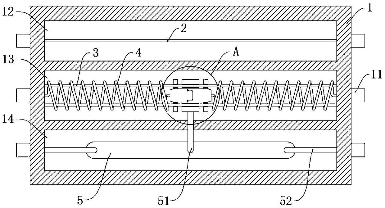
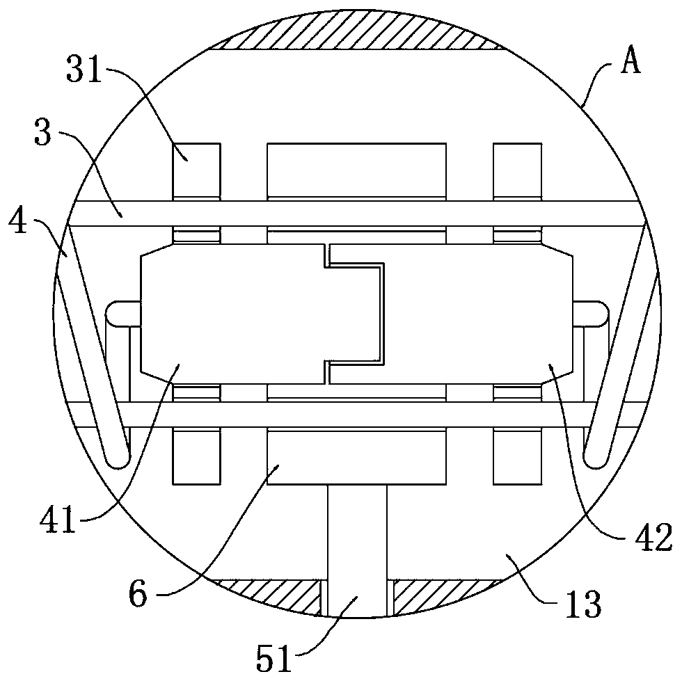
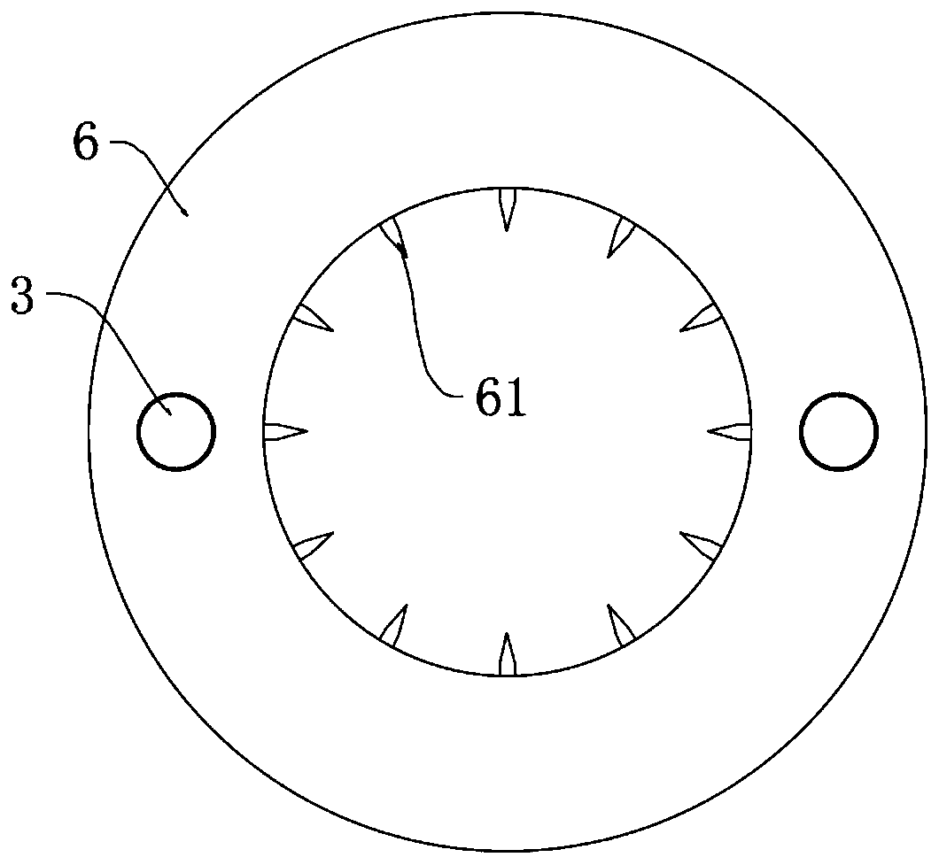
[0032] refer to Figure 1-3 , a short-circuit protection device, including a housing 1, a neutral chamber 12, a protection chamber 13, and a grounding chamber 14 are respectively opened in the housing 1 from top to bottom, a neutral wire 2 is installed in the neutral chamber 12, and a grounding chamber 14 A grounding piece 5 is installed inside, and a protective wire 51 and two symmetrical grounding wires 52 are respectively installed on the grounding piece 5. Three pairs of terminal posts 11 are symmetrically installed on the side wall of the housing 1, and two The slide bar 3, two spring wires 4 are symmetrically wound around the two slide bars 3, and the opposite ends of the two spring wires 4 are respectively equipped with a magnetic plug 41 and a magnetic sleeve 42, and the magnetic plug 41 and the magnetic sleeve 42 are equipped with Sliding board 31, and sliding board 31 is slidably installed on two sliding bars 3, and protective ring 6 is installed on two sliding bars ...

Embodiment 2

[0042] refer to Figure 4-7 , a short-circuit protection device, which is basically consistent with Embodiment 1, the difference is that:

[0043] One of the sliding rods 3 is rotationally connected with the housing 1. The side wall of the housing 1 is provided with a transmission chamber 15. One of the sliding rods 3 extends into the transmission chamber 15 and is equipped with a driven gear 151. The transmission chamber 15 rotates Rotating shaft 152 is installed, and one end of rotating shaft 152 located in transmission chamber 15 is equipped with driving gear 153. One end of rotating shaft 152 extends to the outside of housing 1 and is equipped with plectrum 155. Resetting torsion spring 154 is installed on rotating shaft 152, one of which The sliding bar 3 is provided with an arc-shaped bayonet 32 ​​, and one of the sliding plates 31 is provided with a lock slot 311 , and a lock spring 312 is installed in the lock slot 311 , and a lock tongue 313 is slidably installed in t...


PUM


Abstract

The invention discloses a short-circuit protection device. The short-circuit protection device includes a housing, a zero line cavity, a protection cavity and a grounding cavity are formed in the housing from top to bottom. A zero line cavity is formed in the housing, a zero line is installed in the zero line cavity, a grounding piece is installed in the grounding cavity, a protection wire and twosymmetrical ground wires are installed on the grounding piece, three pairs of binding posts are symmetrically installed on the side wall of the housing, two sliding rods are symmetrically installed in the protection cavity, and two spring wires are jointly and symmetrically wound on the two sliding rods. According to the short-circuit protection device, the magnetic field of the spring wire is enhanced by increasing the short-circuit current to contract and disconnect the magnetic plug and the magnetic sleeve head; after the short-circuit current is eliminated, the magnetic field is weakened,so that the spring wire rebounds to push the magnetic plug and the magnetic sleeve head to connect a circuit, the short-circuit self-recovery function is realized, and the safety of short-circuit protection is improved through a protection ring.

Description

technical field [0001] The invention relates to the field of electricity safety, in particular to a short-circuit protection device. Background technique [0002] In the case of electricity consumption, various improper operations or long-term aging of equipment will cause short circuit of the line, which will generate a large current, which may burn out the electrical equipment or cause a fire. [0003] Existing short-circuit protection devices mostly use air switches, but the air switches cannot be automatically turned on again after short-circuit protection, and need to be turned on manually. For inter-factory equipment, the increase in power-off time will reduce production capacity and affect factory profits. Contents of the invention [0004] The purpose of the present invention is to solve the disadvantages in the prior art that it needs to be manually opened after the short-circuit protection action is triggered, which is relatively inconvenient, and proposes a shor...

Claims


Application Information

Patent Timeline
Patent Type & Authority Applications(China)
IPC IPC(8): H01H3/28H01H9/30H01H3/02H01H9/20
CPCH01H3/28H01H9/30H01H3/02H01H9/20
Inventor 吴军张琼
Owner 深圳市中创电测技术有限公司
Why Eureka
Try Eureka