
500kV compact-to-conventional line strain tower jumper drainage bus fitting

A compact, tower jumper technology, applied in the direction of adjusting/maintaining mechanical tension, cable suspension device, etc., can solve the problems of difficult implementation, low operation safety and reliability, poor shunt effect, etc., and achieve high operation reliability, Good converging effect and uniform current distribution

Pending Publication Date: 2020-07-31
CEEC HUNAN ELECTRIC POWER DESIGN INST
View PDF0 Cites 0 Cited by
  • Summary
  • Abstract
  • Description
  • Claims
  • Application Information

AI Technical Summary

Problems solved by technology

[0002] As the channel space of transmission lines becomes increasingly tight, more and more lines adopt compact technical solutions to compress the space of transmission line corridors. Compact 500kV lines often use six-split conductors, while conventional 500kV lines often use four-split conductors. When compact When the line needs to be connected with the conventional line, it is very difficult to jump through the wires of the two split numbers at the strain tower. The current solution is: by converging the wires with different split numbers into the split wires of the greatest common divisor, that is, in the six-split On the wire side, two 3-to-1 equipment clips are used to merge into two sub-wires, and on the four-split wire side, two 2-to-1 equipment clips are used to merge into two sub-wires, and then jump through the two sub-wires. This technical solution The construction of wire clips for medium 3 to 1 and 2 to 1 equipment is difficult, the diversion effect is poor, and the operation safety and reliability are low

Method used


Image

  • 500kV compact-to-conventional line strain tower jumper drainage bus fitting
  • 500kV compact-to-conventional line strain tower jumper drainage bus fitting
  • 500kV compact-to-conventional line strain tower jumper drainage bus fitting

Examples


Embodiment Construction

[0017] The present invention will be described in further detail below in conjunction with the accompanying drawings and embodiments.

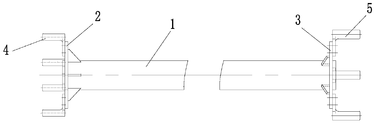
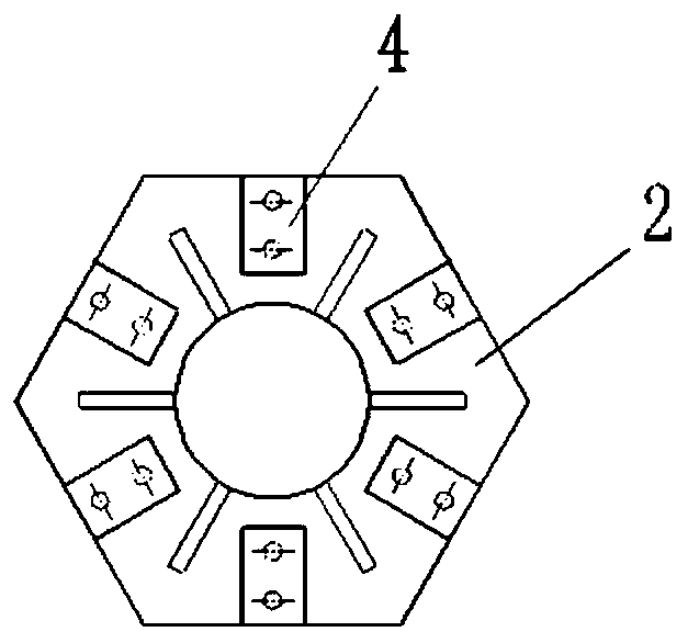
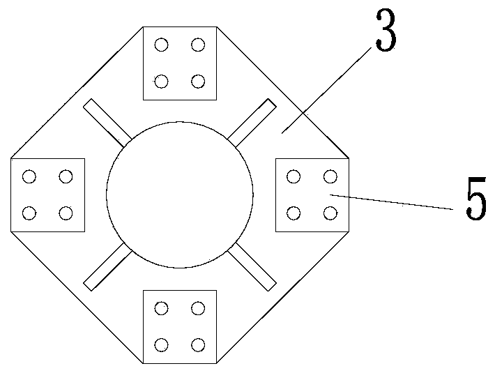
[0018] Refer to attached Figure 1-3 , this embodiment includes a six-split wire confluence plate 2 and a four-split wire confluence plate 3 connected to the two ends of the current-carrying aluminum tube bus 1, the six-split wire confluence plate 2 is provided with a six-split wire equipment clip 4, and the The outside of the four-split wire confluence plate 3 is provided with a four-split wire equipment clip 5, and the six-split wire equipment clip 4 is used to install a six-split wire (not shown in the figure) of a compact line, and the current collection of the six-split wire To the six-split wire confluence plate 2, the collected current is transported to the four-split wire confluence plate 3 through the current-carrying aluminum tube bus 1, and the four-split wire device clip 4 is installed with a conventional line four-split wire (not ...


PUM

PropertyMeasurementUnit
Lengthaaaaaaaaaa

Abstract

The invention relates to a 500kV compact-to-conventional line strain tower jumper drainage bus fitting, which comprises a six-bundle conducting wire confluence disc and a four-bundle conducting wire confluence disc which are connected to two ends of a current-carrying aluminum tube bus, a six-bundle conducting wire equipment wire clamp is arranged on the outer side of the six-bundle conducting wire confluence disc, a four-bundle conducting wire equipment wire clamp is arranged on the outer side of the four-bundle conducting wire confluence disc, the six-bundle conducting equipment wire clamp is used for installing a six-bundle conducting wire of a compact line, the current of the six-bundle conducting wire is gathered to the six-bundle conducting wire confluence disc, the gathered currentis transmitted to the four-bundle conducting wire confluence disc through the current-carrying aluminum tube bus, and a conventional line four-bundle conducting wire is installed on the four-bundle conducting wire equipment wire clamp. According to the invention, firm connection between the conducting wire equipment wire clamp and the bundled conducting wire confluence disc can be realized, and the operation reliability is high; and the bundled conducting wire is good in confluence effect, and current distribution of each sub-conducting wire is uniform.

Description

technical field [0001] The invention relates to the field of power transmission line accessories, in particular to a 500kV compact-to-conventional line tension tower jumper wire diversion busbar fitting. Background technique [0002] As the channel space of transmission lines becomes increasingly tight, more and more lines adopt compact technical solutions to compress the space of transmission line corridors. Compact 500kV lines often use six-split conductors, while conventional 500kV lines often use four-split conductors. When compact When the line needs to be connected with the conventional line, it is very difficult to jump through the wires of the two split numbers at the strain tower. The current solution is: by converging the wires with different split numbers into the split wires of the greatest common divisor, that is, in the six-split On the wire side, two 3-to-1 equipment clips are used to merge into two sub-wires, and on the four-split wire side, two 2-to-1 equipm...

Claims


Application Information

Patent Timeline
IPC IPC(8): H02G7/02H02G7/05
CPCH02G7/02H02G7/05
Inventor 梁盼望杨力徐鹏唐春林李辉徐志鸿刘庆丰胡涛
Owner CEEC HUNAN ELECTRIC POWER DESIGN INST
Learn More