Receiver and communication equipment

A receiver and channel technology, applied in the field of communication, can solve the problems affecting communication quality, resource-consuming digital signal processing, and impact on anti-jamming performance, so as to improve the second-order intermodulation intercept point, reduce the impact of sensitivity, and enhance anti-jamming. effect of ability

Active Publication Date: 2020-07-31
HYTERA COMM CORP
View PDF3 Cites 6 Cited by
  • Summary
  • Abstract
  • Description
  • Claims
  • Application Information

AI Technical Summary

Problems solved by technology

[0003] The inventor of the present application has found in the long-term research and development that the solution of adding an attenuator directly before the mixer can be adopted in the prior art, and the solution is achieved by adding an attenuator directly before the mixer (before or after the low noise amplifier). Improve the second-order intermodulation intercept point (IP2, Second-order Input Intercept Point) index; the disadvantage is that the sensitivity of the system is reduced, which will seriously affect the communication quality when the useful signal is weak
In addition, you can also use the figure 1 In the technical solution shown, the main signal is compensated through the second signal path, and a compensation signal is generated by the second signal path, and a calibration signal is superimposed on the main signal, thereby eliminating the interference of the baseband; the disadvantages of this technology It is necessary to dynamically adjust the parameters of the variable gain amplifier (VGA, Variable Gain Amplifier) ​​to make the calibration signal effective in real time, which will consume a lot of resources and require higher computing power for digital signal processing (DSP, Digital Signal Processing)
In addition, the implementation of the control algorithm is also difficult, and a bad algorithm will have a great impact on the anti-interference performance

Method used


Image

  • Receiver and communication equipment
  • Receiver and communication equipment
  • Receiver and communication equipment

Examples


Embodiment Construction

[0015] The following will clearly and completely describe the technical solutions in the embodiments of the present application with reference to the drawings in the embodiments of the present application. Obviously, the described embodiments are only some of the embodiments of the present application, not all of them. Based on the embodiments in this application, all other embodiments obtained by persons of ordinary skill in the art without making creative efforts belong to the scope of protection of this application.

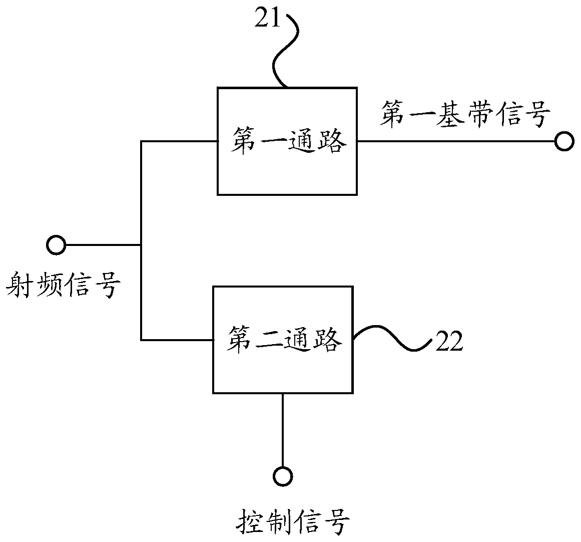
[0016] refer to figure 2 , figure 2 It is a schematic structural diagram of an embodiment of a receiver provided in this application, and the receiver includes: a first path 21 and a second path 22 .

[0017] The first channel 21 is used to receive a radio frequency signal, and generate a first baseband signal according to the radio frequency signal; wherein, the radio frequency signal includes a useful signal and at least two interference signals, and the ...


PUM


Abstract

The application discloses a receiver and communication equipment. The receiver comprises a first path and a second path. The first path is used for receiving radio frequency signals and generating baseband signals according to the radio frequency signal; the radio frequency signals comprise a useful signal and at least two interference signals, and the baseband signals comprise a difference frequency signal between the at least two interference signals. And the second path is used for receiving the radio frequency signals and determining whether to attenuate the radio frequency signals received by the second path according to the control signal so as to reduce the signal intensity of the interference signal in the second path, and the control signal is determined according to the signal intensity of the baseband signal generated by the first path. Through the above mode, the second-order intermodulation intercept point of the receiver can be improved, the anti-interference capability is enhanced, and the influence on the sensitivity of the receiver is reduced.

Description

technical field [0001] The present application relates to the technical field of communication, and in particular to a receiver and a communication device. Background technique [0002] In modern receivers, zero intermediate frequency (ZIF, Zero Intermediate Frequency) architecture has many advantages, such as high integration, low cost and simpler circuit structure. Even so, it still has some serious problems, among which poor immunity to interference is a major factor hindering the large-scale application of receivers with this architecture. More specifically, for interference like two-tones that exist in-band, due to the inherent structure of zero-IF receivers, low-frequency interference signals will be generated at baseband. [0003] The inventor of the present application has found in the long-term research and development that the solution of adding an attenuator directly before the mixer can be adopted in the prior art, and the solution is achieved by adding an atten...

Claims


Application Information

Patent Timeline
Patent Type & Authority Applications(China)
IPC IPC(8): H04B1/12H04B1/30
CPCH04B1/126H04B1/30
Inventor 王冠高存浩尤国雄
Owner HYTERA COMM CORP
Why Eureka
Try Eureka