Chip mounting device for electronic component production and chip mounting method of chip mounting device

A technology for electronic components and placement devices, which is applied in the direction of assembling printed circuits with electrical components, electrical components, printed circuits, etc., which can solve the problem of inability to fix the circuit board and reduce the application of automatic placement machines for electronic components placement and processing. range, no fixed adjustment structure, etc., to achieve the effect of high patch efficiency, strong practicability, and wide application range

Active Publication Date: 2020-07-31
安徽新芯威半导体有限公司
View PDF6 Cites 4 Cited by
  • Summary
  • Abstract
  • Description
  • Claims
  • Application Information

AI Technical Summary

Problems solved by technology

[0005] The existing automatic placement machine for electronic component placement and processing does not have a fixed adjustment structure, which reduces the scope of application of the automatic placement machine for electronic component placement and processing, making it unable to perform fixed operations on circuit boards of different sizes. bring certain adverse effects to users

Method used


Image

  • Chip mounting device for electronic component production and chip mounting method of chip mounting device
  • Chip mounting device for electronic component production and chip mounting method of chip mounting device
  • Chip mounting device for electronic component production and chip mounting method of chip mounting device

Examples


Embodiment Construction

[0030] The following will clearly and completely describe the technical solutions in the embodiments of the present invention with reference to the accompanying drawings in the embodiments of the present invention. Obviously, the described embodiments are only some, not all, embodiments of the present invention. Based on the embodiments of the present invention, all other embodiments obtained by persons of ordinary skill in the art without making creative efforts belong to the protection scope of the present invention.

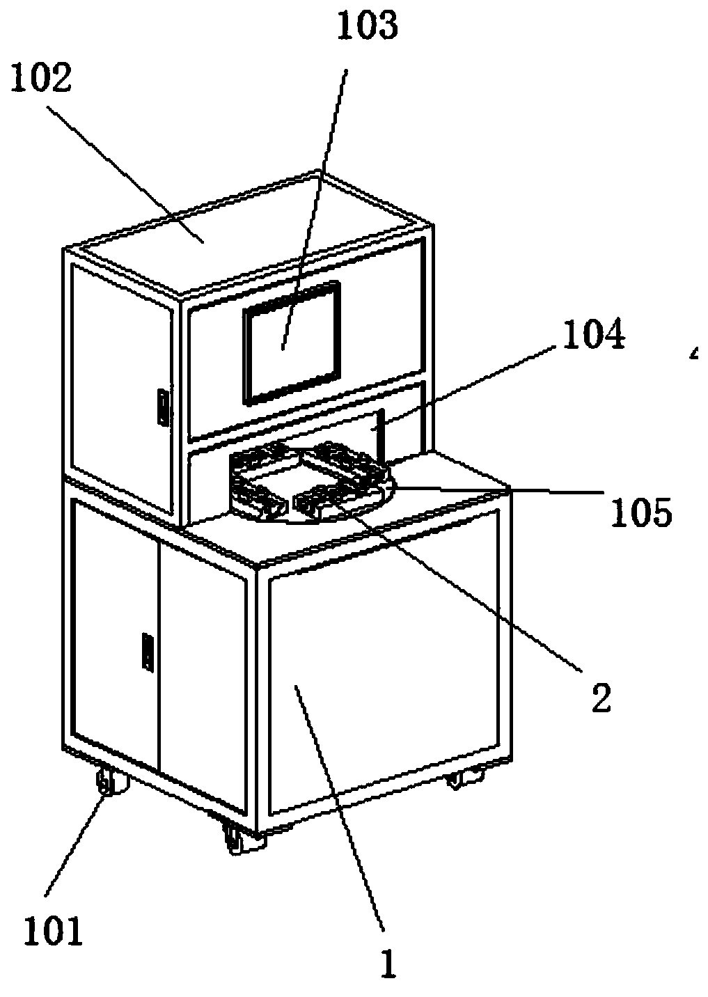
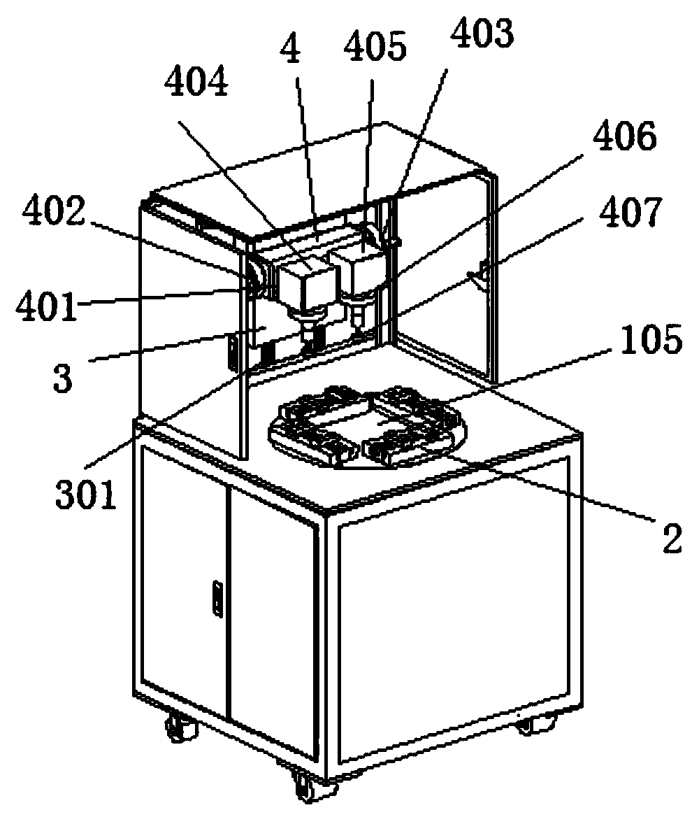
[0031] see Figure 1-7 , in an embodiment of the present invention, a patch device for the production of electronic components includes a main chassis 1, a patch cavity 102 is fixedly arranged on the top surface of the main chassis 1, and the interior of the patch cavity 102 A mobile platform 3 is slidably connected to the rear side, and a horizontal fixed frame 4 is fixedly arranged on the front of the mobile platform 3, and a main fixed platform 404 and an a...


PUM


Abstract

The invention discloses a chip mounting device for electronic component production. The device comprises a main case; a patch cavity is fixedly formed in the top surface of the main case; a movable rack is connected with the rear side surface of the interior of the patch cavity in a sliding manner; a transverse fixing frame is fixedly arranged on the front face of the movable rack; a main fixing table and an auxiliary fixing table are arranged on the transverse fixing frame side by side; the main fixing table and the auxiliary fixing table are each provided with an air cylinder; a suction cupis fixedly arranged on a piston rod of each air cylinder; a motor I is fixedly arranged in a cavity of the main case; the output end of the motor I is fixedly connected with the center of the bottom face of a rotary disc; the rotary disc penetrates through the upper surface of the main case; and four sets of workpiece mounting tables are arranged on the disc face of the rotary disc at equal angles. The chip mounting device for electronic component production achieves non-stop operation, and is high in practicability and chip mounting efficiency.

Description

technical field [0001] The invention belongs to the technical field of automatic placement technology, in particular to a placement device for the production of electronic components. Background technique [0002] The placement machine is also called the placement machine. In the production line, the placement machine is configured after the dispensing machine or the screen printing machine. It is a device that accurately places the surface mount components on the PCB pad by moving the placement head. . Divided into manual and fully automatic two. [0003] For example, the comparative document CN208521947U discloses an automatic placement machine, which is suitable for placement between solar cells and glass cover plates. The automatic placement machine includes a left placement station, a right placement station, a positioning platform, SMT manipulator, gluing mechanism and squeegee mechanism, the left and right placement stations are set at intervals, any placement stati...

Claims


Application Information

Patent Timeline
Patent Type & Authority Applications(China)
IPC IPC(8): H05K3/30H05K3/00
CPCH05K3/0008H05K3/30
Inventor 罗白强熊伟宋羽嘉
Owner 安徽新芯威半导体有限公司
Why Eureka
Try Eureka