Infusion bottle automatic shaking device for insulin intravenous injection

A technology for infusion bottles and insulin, which is applied in transportation and packaging, hypodermic injection equipment, shaking/oscillating/vibrating mixers, etc., and can solve problems such as laborious and troublesome operations

Active Publication Date: 2020-08-04
THE AFFILIATED HOSPITAL OF SHANDONG UNIV OF TCM
View PDF13 Cites 10 Cited by
  • Summary
  • Abstract
  • Description
  • Claims
  • Application Information

AI Technical Summary

Problems solved by technology

[0005] In order to overcome the shortcomings of manually shaking the infusion bottle to make the insulin uniform, the hand needs to be constantly waved, which is laborious and troublesome to operate. , and convenient automatic shaking device for infusion bottle for intravenous injection of insulin

Method used


Image

  • Infusion bottle automatic shaking device for insulin intravenous injection
  • Infusion bottle automatic shaking device for insulin intravenous injection
  • Infusion bottle automatic shaking device for insulin intravenous injection

Examples


Embodiment 1

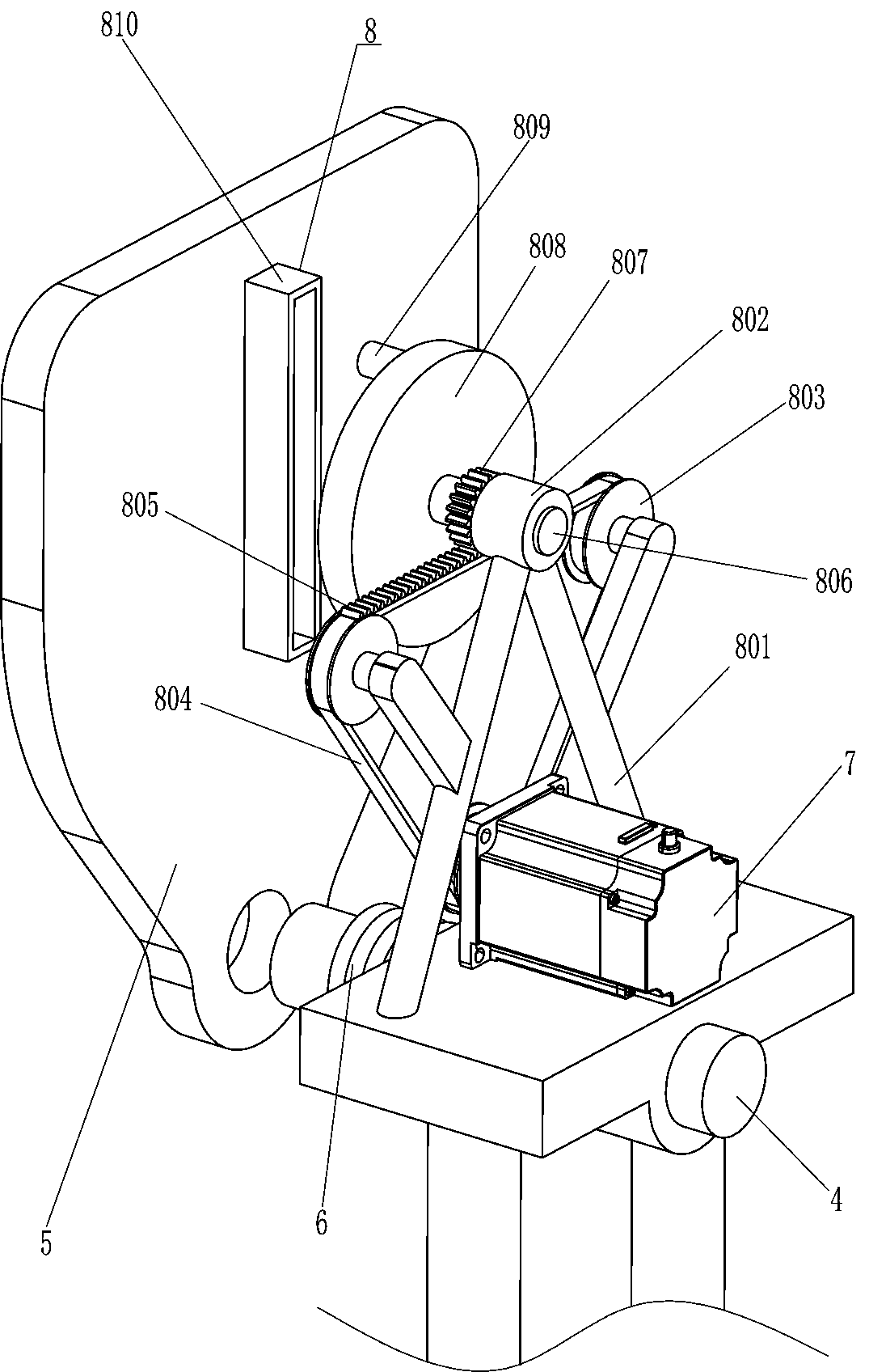
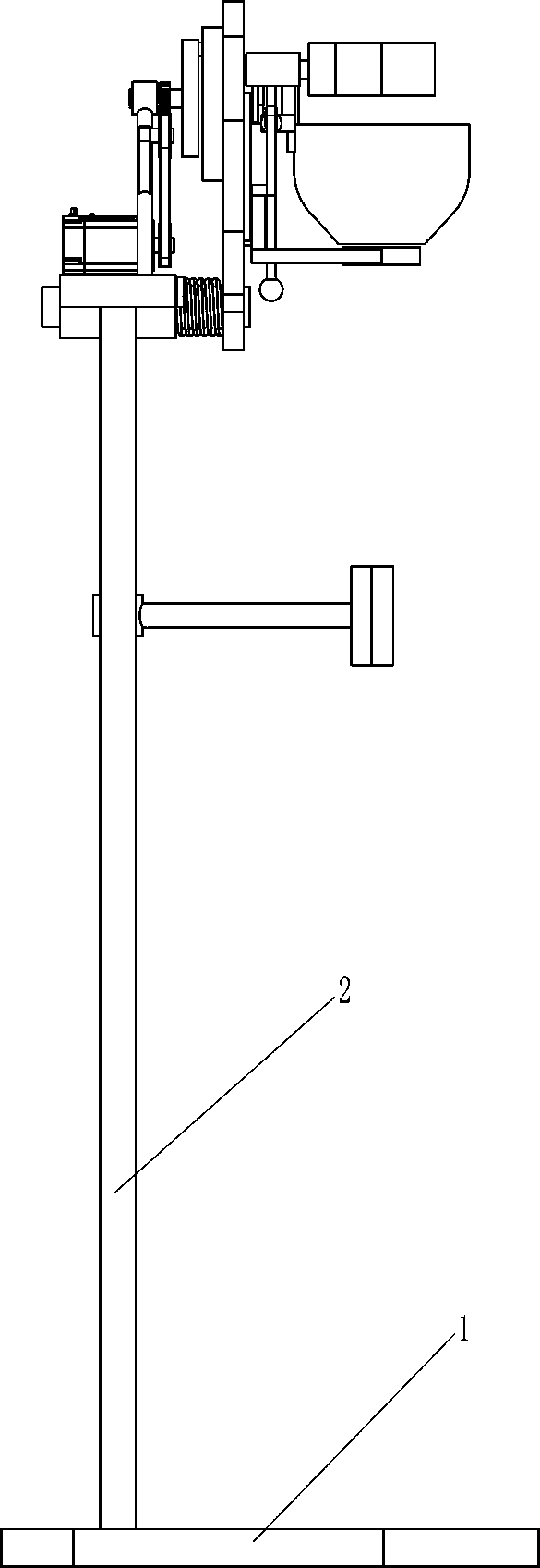
[0027] refer to Figure 1-Figure 8 , an automatic shaking device for an infusion bottle for insulin intravenous injection, comprising a bottom plate 1, a pole 2, a support plate 3, a first rotating shaft 4, a mounting plate 5, a torsion spring 6, a servo motor 7, a rotating assembly 8 and a fixing assembly 9 , two support rods 2 are fixedly connected to the left side of the top of the bottom plate 1, a support plate 3 is fixedly connected between the tops of the two support rods 2, a first rotating shaft 4 is connected to the middle of the bottom of the supporting plate 3 in a rotational manner, and the right end of the first rotating shaft 4 A mounting plate 5 is fixedly connected, a torsion spring 6 is connected between the left side of the mounting plate 5 and the right side of the support plate 3, the torsion spring 6 is set on the first rotating shaft 4, the left side of the mounting plate 5 is connected to the top of the support plate 3 There is a rotating assembly 8 bet...

Embodiment 2

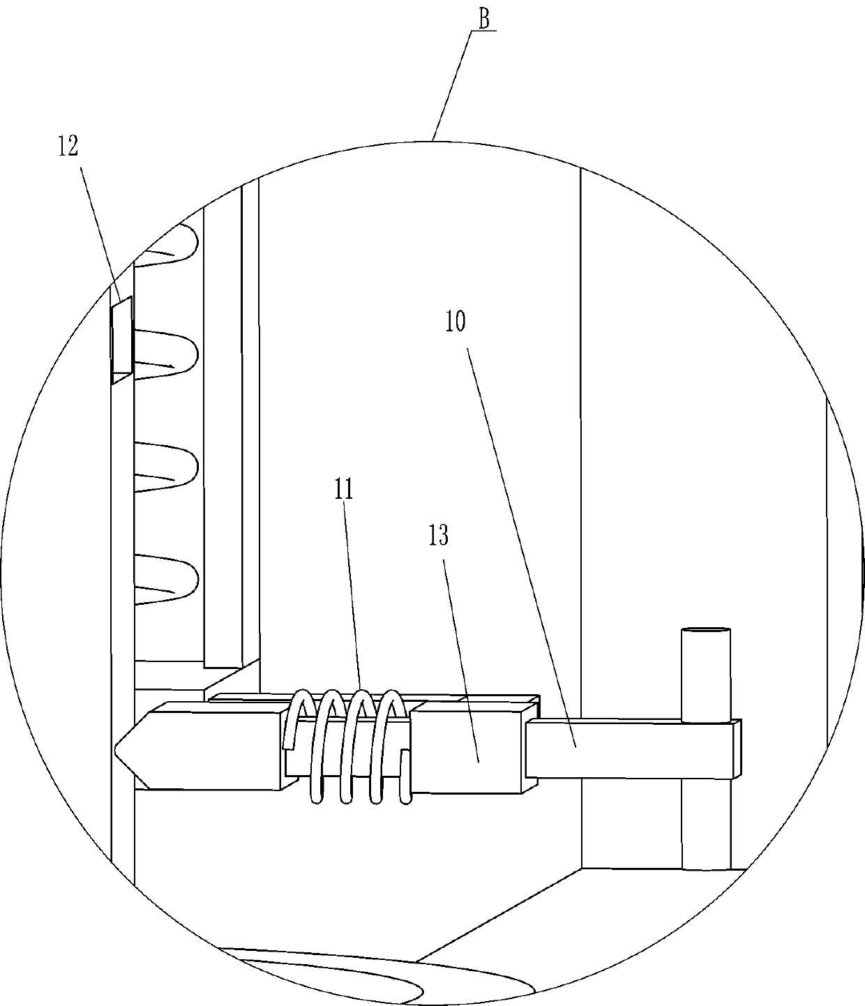
[0034] refer to Figure 5 and Figure 9 Compared with Embodiment 1, the main difference of this embodiment is that in this embodiment, a clamping rod 10, a fifth spring 11 and a guide sleeve 13 are also included, and the guide sleeve 13 is fixedly connected to the lower right side of the rear side of the guide rail 903, and the guide sleeve 13 inner sliding type is provided with clamping rod 10, and clamping rod 10 is positioned at T-shaped push rod 909 rear side, is wound with the fifth spring 11 between the front part of clamping rod 10 and the front side of guide sleeve 13, behind T-shaped push rod 909 A draw-in slot 12 is formed on the lower part of the side, and the draw-in slot 12 cooperates with the draw bar 10 .

[0035] Initially, the fifth spring 11 is in a compressed state. When the T-shaped push rod 909 moves downward, the T-shaped push rod 909 also drives the card slot 12 to move downward. When the card slot 12 moves down to the front side of the card rod 10 , d...


PUM


Abstract

The invention relates to a shaking device, in particular to an infusion bottle automatic shaking device for insulin intravenous injection. The infusion bottle automatic shaking device for insulin intravenous injection can replace manual work to shake the infusion bottle so that insulin can be uniform, labor can be saved, and convenience can be achieved. The infusion bottle automatic shaking devicefor insulin intravenous injection comprises a bottom plate, supporting rods are symmetrically and fixedly connected to the edge of one side of the bottom plate, a supporting plate is installed between the ends, away from the bottom plate, of the two supporting rods, and a first rotating shaft is rotatably installed in the middle, facing the bottom plate, of one side of the supporting plate. An infusion bottle is placed in the supporting cover, the clamping block makes contact with the infusion bottle to clamp the infusion bottle, when shaking is needed, the servo motor is started, the mounting plate can swing front and back, then the clamping block drives the infusion bottle to swing to evenly shake insulin, the infusion bottle does not need to be shaken manually, labor is saved, and convenience is achieved.

Description

technical field [0001] The invention relates to a shaking device, in particular to an automatic shaking device for an infusion bottle for intravenous injection of insulin. Background technique [0002] Infusion bottle: The infusion bottle is used for the bottle of the medically prepared liquid in the human body during the infusion of the patient. The medical glass infusion bottle packaging has a history of 100 years. Glass products made of inorganic materials fired at 1600°C are used as medicinal containers with the characteristics of smoothness, easy disinfection, corrosion resistance, wear resistance, stable size, excellent chemical stability, non-toxic and harmless, and are traditional medical packaging materials. , In the intravenous infusion, insulin will be added to the infusion bottle, but in order to avoid the patient's hypoglycemia reaction after the infusion, the insulin will be shaken to make it even. [0003] For example, the published article number on March 25...

Claims


Application Information

Patent Timeline
Patent Type & Authority Applications(China)
IPC IPC(8): A61M5/14B01F11/00
CPCA61M5/1415A61M5/1418A61M5/1417B01F31/201B01F31/26
Inventor 不公告发明人
Owner THE AFFILIATED HOSPITAL OF SHANDONG UNIV OF TCM
Why Eureka
Try Eureka