A kind of plastic plate processing and trimming equipment
What is Al technical title?
Al technical title is built by PatSnap Al team. It summarizes the technical point description of the patent document.
A technology of plastic board and edge trimming, which is applied in the field of plastic processing and can solve problems such as damage effects
Active Publication Date: 2021-10-08
山东归仁新型材料科技有限公司
View PDF7 Cites 1 Cited by
Summary
Abstract
Description
Claims
Application Information
AI Technical Summary
This helps you quickly interpret patents by identifying the three key elements:
Problems solved by technology
Method used
Benefits of technology
Problems solved by technology
[0004] Because some synthetic boards are stacked, one end is stuck inside, and the other end is exposed in the shape of a fish scale. When trimming the plastic board in this form, the force of its rotation is easy to lift its small body and damage the overall structure. Effect
Method used
Image
Click on the blue label to locate the original text in one second.
Reading with bidirectional positioning of images and text.
Examples
Embodiment 1
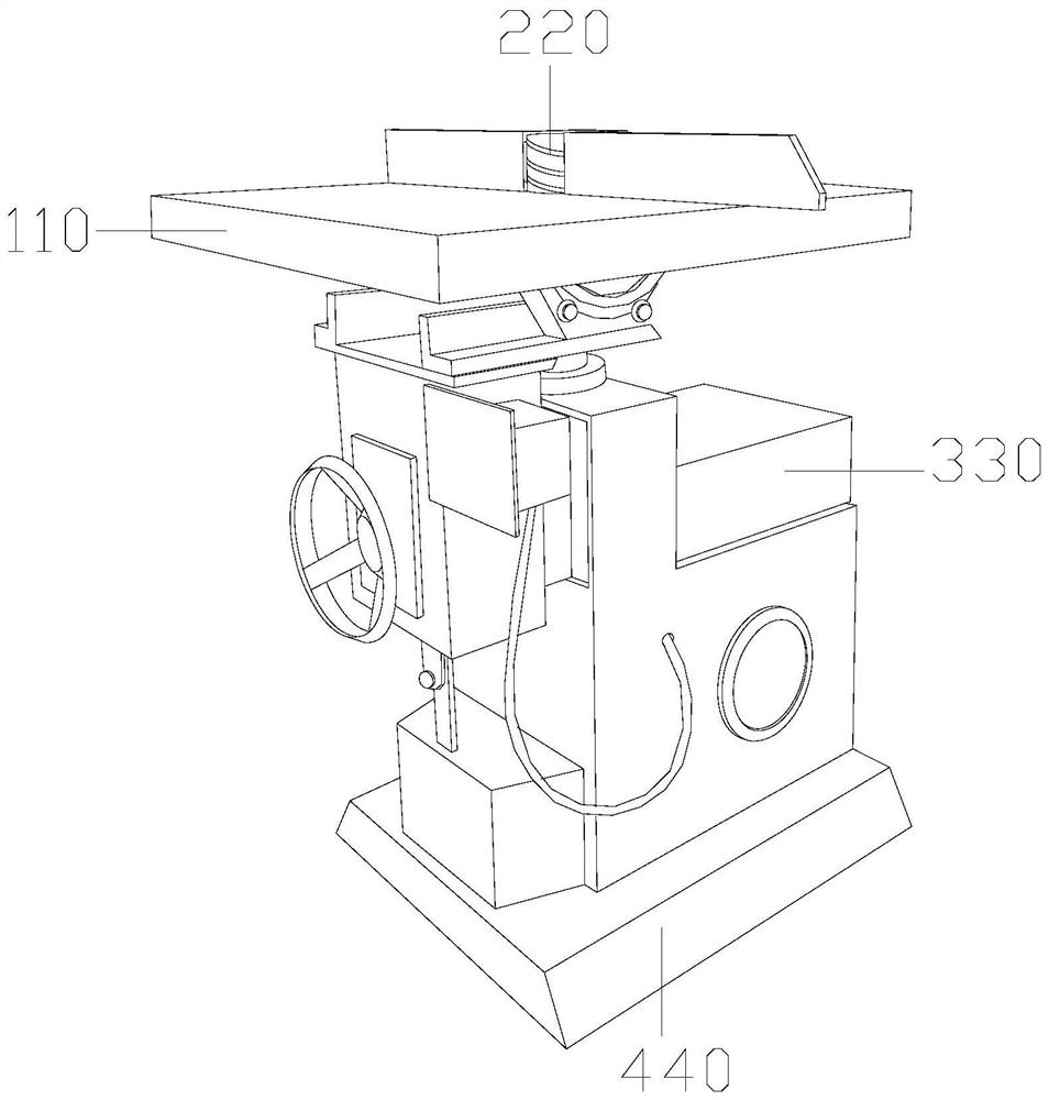
[0032] as attached figure 1 to attach Image 6 Shown:
[0033] The present invention provides a plastic board processing and trimming equipment, the structure of which includes a workbench 110 , a trimming wheel 220 , a control box 330 , and a base 440 .
[0034] The trimming wheel 220 vertically penetrates the inside of the workbench 110 , the bottom end of the workbench 110 is welded to the upper surface of the control box 330 , and the end of the control box 330 away from the workbench 110 is connected to the base 440 .
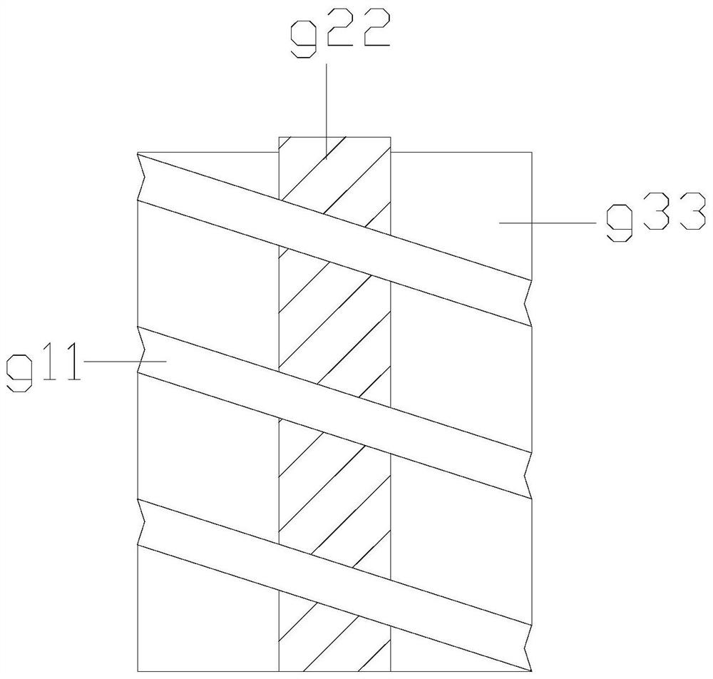
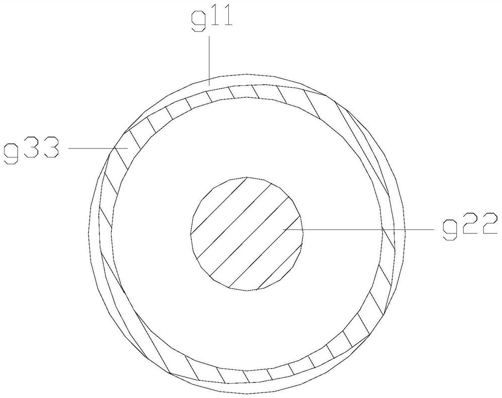
[0035] Wherein, the trimming wheel 220 includes a grinding path g11, a center column g22, and a grinding block g33. The grinding path g11 touches the surface of the grinding block g33. Located on the same axis as the grinding block g33, the winding state of the grinding track g11 is evenly distributed, the central column g22 fixes the center point of the overall rotation, and the grinding block g33 as a whole performs friction trimming against external o...
Embodiment 2
[0042] as attached Figure 7 to attach Figure 9 Shown:
[0043] Wherein, the grinding block g33 includes a pendulum angle 001 and an abutment angle 002, the abutment angle 002 is attached to the inner surface of the pendulum angle 001, four of the abutment angles 002 are provided and two form a group, and the pendulum angle There are two angles 001. The swing angle 001 is fixed at one position. When force is applied on both sides, it will be stretched. The angle 002 allows the external force to be better wrapped and displayed.
[0044] Wherein, the swing angle 001 includes a swing angle x11, a clamping block x22, and a total force layer x33, and the swing angle x11 is installed between two clamping blocks x22 at intervals, and the clamping block x22 and the inner wall of the total force layer x33 connected, the swing angle x11 is against the inner wall of the total force layer x33, the clamping block x22 is a quadrilateral structure, there are five swing angle x11, and the ...
PUM
Abstract
The invention discloses a plastic plate processing and trimming equipment. The structure includes a workbench, a trimming wheel, and a control box. The trimming wheel vertically runs through the inside of the workbench. When the edge wheel rotates, its plastic plate moves along the surface of the trimming wheel, and its scale-shaped combination piece will be stuck into the inside of the grinding channel along the moving direction. When the combination plate passes through the smooth opening, it will be stuck between the inside of the joint rod When the outer inclined part is snapped in, when the plastic board continues to move backward, when the finished plastic composite board is trimmed, the main part and the composite sheet can be separated, so that it will not be oppressed, and it will be When it is placed in the inner road of the mill, it will exert force on the corner, so that the external force can be better wrapped and exerted. The arc will be bent by the force, and its spacer will squeeze the spacer, evenly By separating the overall force-bearing pulling surface, the equipment can adjust the slope of the object according to the object when the object has a different slope and is moved in for trimming.
Description
technical field [0001] The invention belongs to the field of plastic processing, and more specifically relates to a plastic plate processing and trimming equipment. Background technique [0002] After the finished plastic board is manufactured, some of the finished plastic boards are in the form of many small plastics integrated into a whole, which can better highlight the three-dimensional effect of the required texture, and the corners need to be trimmed to a certain extent. Let it move on the platform of the equipment by the plastic plate at the desired level, let the swivel grind its plate. [0003] Based on the above-mentioned inventor's discovery, the existing plastic plate processing and trimming equipment mainly has the following deficiencies, such as: [0004] Because some synthetic boards are stacked, one end is stuck inside, and the other end is exposed in the shape of a fish scale. When trimming the plastic board in this form, the force of its rotation is easy t...
Claims
Application Information
Patent Timeline
Application Date:The date an application was filed.
Publication Date:The date a patent or application was officially published.
First Publication Date:The earliest publication date of a patent with the same application number.
Issue Date:Publication date of the patent grant document.
PCT Entry Date:The Entry date of PCT National Phase.
Estimated Expiry Date:The statutory expiry date of a patent right according to the Patent Law, and it is the longest term of protection that the patent right can achieve without the termination of the patent right due to other reasons(Term extension factor has been taken into account ).
Invalid Date:Actual expiry date is based on effective date or publication date of legal transaction data of invalid patent.