Hematopoietic stem cell storing and pairing device

A technology for hematopoietic stem cells and storage boxes, which is applied in the directions of unloading devices, packaging, internal accessories, etc., can solve the problems of taking a long time and the hematopoietic stem cells are easily polluted by the outside world, and achieves pollution prevention, accurate selection, and convenient access. Effect

Inactive Publication Date: 2020-08-04
李容尔
View PDF7 Cites 5 Cited by
  • Summary
  • Abstract
  • Description
  • Claims
  • Application Information

AI Technical Summary

Problems solved by technology

[0003] Most of the hematopoietic stem cells are stored in the blood bank before pairing. Since there are many blood samples in the blood bank, it will take a long time to take out

Method used


Image

  • Hematopoietic stem cell storing and pairing device
  • Hematopoietic stem cell storing and pairing device
  • Hematopoietic stem cell storing and pairing device

Examples


Embodiment 1

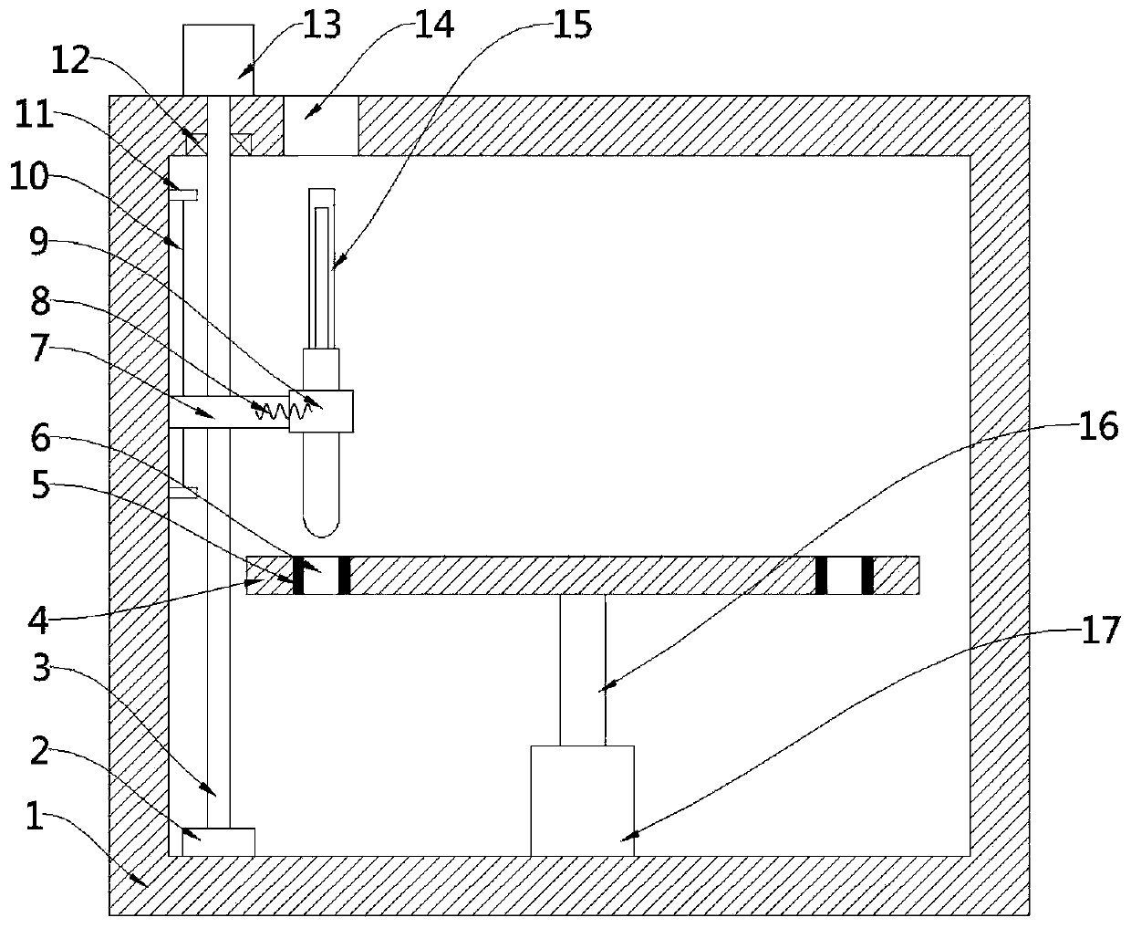
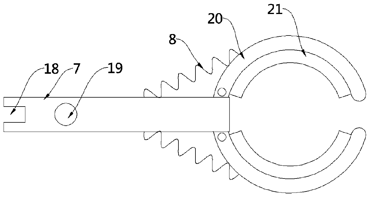
[0027] see Figure 1-2 , this embodiment provides a hematopoietic stem cell storage matching device, including a storage box 1, the upper wall of the storage box 1 is provided with a pick-and-place opening 14, and a test tube installation component and a test tube pick-and-place component are arranged inside the storage box 1, specifically , the test tube installation assembly includes a storage rack 4 and a second motor 17 arranged at the bottom of the storage rack 4 and connected to the storage rack 4 through a rotating shaft 16, and the storage rack 4 is distributed in a circular array. The clamping hole 6 of the fixed test tube; the test tube pick-and-place assembly includes a clamping assembly 9 and a first drive assembly that controls the movement of the clamping assembly 9 up and down. Specifically, the clamping assembly includes a drive plate 7 and a rotating device Two groups of symmetrically arranged splints 20 at one end of the drive plate 7, the sides of the two se...

Embodiment 2

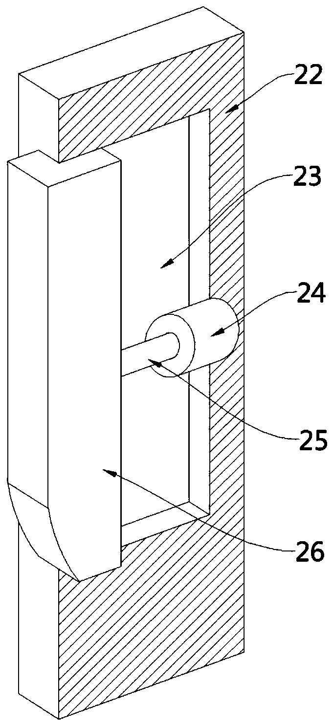
[0042] see figure 1 with image 3 , a pairing device for hematopoietic stem cell storage. Compared with Embodiment 1 in this embodiment, a second driving assembly 15 for driving two sets of splints 20 to close each other is provided inside the storage box 1 .

[0043] When the driving rod 3 drives the driving plate 7 to move upward to the bottom of the pick-and-place opening 14, place the test tube between the two groups of splints 20, and through the reverse rotation of the driving rod 3, drive the driving plate 7 and the splint 20 to move downward, and simultaneously use The second driving assembly 15 drives the two sets of splints 20 to close, and clamps the test tube until the test tube moves down and is inserted into the clamping hole 6 .

[0044] Specifically, the second driving assembly 15 includes a fixed base 22 fixedly arranged on the inner wall of the storage box 1, and an inner cavity 23 is arranged inside the fixed base 22, and the inner cavity 23 extends to the fi...


PUM


Abstract

The invention provides a hematopoietic stem cell storing and pairing device, and belongs to the technical field of medical equipment. The hematopoietic stem cell storing and pairing device comprises astorage box, a take-placing opening is formed in the upper wall of the storage box, and a test tube mounting assembly and a test tube take-placing assembly are arranged in the storage box. The test tube mounting assembly comprises a storage rack and a second motor which is arranged at the bottom of the storage rack and is connected with the storage rack through a rotary shaft. The hematopoietic stem cell storing and pairing device has the advantages that taking and placing are convenient, and the storage effect is good; when a test tube needs to be taken out, the second motor drives the storage rack to rotate, the test tube needing to be taken out is moved to be below clamping plates, a driving rod drives a driving plate to move downwards, and the clamping plates are utilized for clampingthe test tube. Then the driving rod drives the driving plate and the clamping plates clamping the test tube to move upwards to the take-placing opening, the test tube can be taken out, and precise selection of the test tube is achieved; and meanwhile all test tube samples are prevented from be exposed to the external environment, and hematopoietic stem cells are prevented from being contaminatedby the external environment.

Description

technical field [0001] The invention belongs to the technical field of medical equipment, in particular to a hematopoietic stem cell storage pairing device. Background technique [0002] At present, the blood station collects a certain amount of hematopoietic stem cells every year. College students are the main group of hematopoietic stem cell donations. Hematopoietic stem cell collection is basically kept at the same time as blood collection. [0003] Most of the hematopoietic stem cells are stored in the blood bank before pairing. Since there are many blood samples in the blood bank, it will take a long time to take out the samples later, and it will also lead to the open state of the whole blood bank, making it easy for the hematopoietic stem cells in the blood bank to receive outside pollution. Contents of the invention [0004] In view of the above-mentioned deficiencies in the prior art, the technical problem to be solved by the embodiments of the present invention ...

Claims


Application Information

Patent Timeline
IPC IPC(8): B65D25/02B65D25/10B65D25/38B65D81/05
CPCB65D25/02B65D25/101B65D25/38B65D81/05
Inventor 李容尔
Owner 李容尔
Why Eureka
Try Eureka