
Shaft tunneling machine and cutter head thereof

A cutter head and cutting tool technology, which is applied in the direction of shaft equipment, sinking, mining equipment, etc., can solve the problems of spending a lot of time cleaning mud, increasing the difficulty of disassembling the cutter head and the dismantling period, and difficult to guarantee the safety of personnel.

Active Publication Date: 2020-08-04
CHINA RAILWAY CONSTR HEAVY IND
View PDF5 Cites 3 Cited by
  • Summary
  • Abstract
  • Description
  • Claims
  • Application Information

AI Technical Summary

Problems solved by technology

However, when the shaft boring machine is excavating the shaft, most of them will use the mud conveying type to discharge the slag. During the dismantling after the shaft excavation is completed, a large amount of mud will accumulate at the bottom of the well and will gradually solidify. Part of the cutter head will be covered by mud. When the cutter head needs to remove the bolts at the joints of the blocks, it will take a lot of time to clean up the mud, which will greatly increase the difficulty of disassembling the cutter head and the dismantling period. At the same time, in the above operations During the process, the construction personnel directly entered the cutter head soil bin at the bottom of the well to work, and the safety of personnel was difficult to guarantee.
[0003] Therefore, how to avoid affecting the work efficiency and the safety of the staff due to the traditional splitting of the cutter head and lifting it out is a technical problem that those skilled in the art need to solve at present.

Method used


Image

  • Shaft tunneling machine and cutter head thereof
  • Shaft tunneling machine and cutter head thereof
  • Shaft tunneling machine and cutter head thereof

Examples


Embodiment Construction

[0032] The following will clearly and completely describe the technical solutions in the embodiments of the present invention with reference to the accompanying drawings in the embodiments of the present invention. Obviously, the described embodiments are only some, not all, embodiments of the present invention. Based on the embodiments of the present invention, all other embodiments obtained by persons of ordinary skill in the art without making creative efforts belong to the protection scope of the present invention.

[0033] The core of the present invention is to provide a cutter head, which can be recovered smoothly after the shaft excavation is completed, so that the dismantling period can be shortened and the safety of construction personnel can be improved. Another core of the present invention is to provide a shaft boring machine comprising the above cutter head.

[0034] In order to enable those skilled in the art to better understand the solution of the present inve...


PUM


Abstract

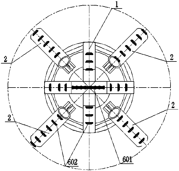
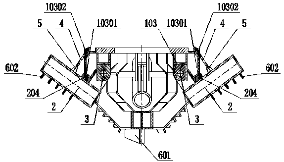
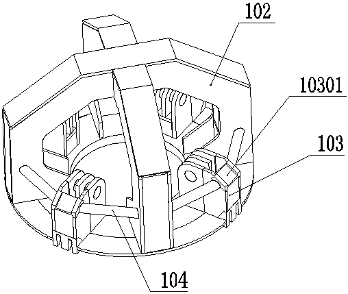
The invention discloses a shaft tunneling machine and a cutter head thereof. The cutter head comprises a middle cutter head body and a plurality of folding spoke arms foldably arranged on the middle cutter head body and used for mounting cutters; any folding spoke arm is connected with a connecting assembly detachably connected to the middle cutter head body; a plurality of bases arranged in one-to-one correspondence with the folding spoke arms are fixedly connected to the middle cutter head body, and any base is hinged to the corresponding folding spoke arm; and any folding spoke arm is provided with a supporting boss, and each base is provided with a concave positioning block combined with the corresponding supporting boss in an embedding mode for positioning the corresponding folding spoke arm. The cutter head is connected with the middle cutter head body through the connecting assemblies, the embedded connection of the concave positioning blocks and the supporting bosses ensures the rigid connection of the whole cutter head, and accordingly the stability of tunneling can be further ensured. Meanwhile, when a shaft is supported or the inner diameter is reduced after pipe segments are assembled, the cutter head can be smoothly recovered, the dismantling construction period can be shortened, the working efficiency can be improved, and the economical efficiency and the personnel safety can be improved.

Description

technical field [0001] The invention relates to the technical field of boring machines, in particular to a cutterhead. The invention also relates to a shaft boring machine with such a cutterhead. Background technique [0002] Shaft boring machines are widely used in shaft construction projects because of their safety and high efficiency. Shaft cutterheads are key equipment for full-section excavation of the bottom surface of shafts. When using a shaft boring machine for shaft construction, as the shaft excavation continues to deepen, the shaft wall needs to be supported. Since the inner diameter of the shaft wall support is smaller than the diameter of the cutter head, after the shaft shaft excavation is completed, The shaft cutter head cannot be hoisted from the shaft to the ground as a whole. The existing method is to design the cutter head as a multi-sided block structure, and bolt each side block through bolts to assemble a whole cutter head; However, when the shaft b...

Claims


Application Information

Patent Timeline
IPC IPC(8): E21D1/03E21D1/06
CPCE21D1/03E21D1/06
Inventor 刘飞香彭正阳暨智勇姚满柯威
Owner CHINA RAILWAY CONSTR HEAVY IND
Learn More